Abaqus 2021 is out. In this blog post, we will be showing some of the enhancements, that we found interesting. Additionally most major enhancements will be highlighted, for this new Abaqus release. For a more in depth explanation of the new enhancements, you can take a look in the release notes, provided here.
The discussed enhancements, are included in versions up to Abaqus 2021 FD03(FP.CFA.2042), which has been released. More enhancements are scheduled for later releases of Abaqus 2021x.
Defining Spatial Distribution of Material Directions
This feature can be used to define a distribution of local material directions (e.g. fiber directions) for an anisotropic material. Additionally this feature can be used to import local material direction results from an output database (*.sim).
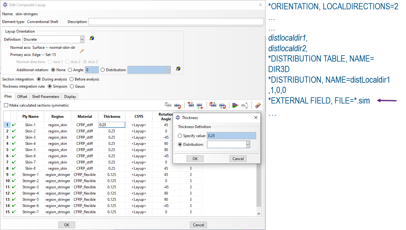
With this feature, the user can assign a varying thickness of individual plies(conventional shells or solid elements) in a composite layup (through the distribution feature). Up till now, varying thickness was supported only for the entire layup thickness. This enhancement is expected to speed up the performance of the composite layup editor, particularly for layups comprising of a large number of plies. A detail of the newly added feature is given in Figure 1, below. It shows the option to spatially vary the thickness of individual plies. To the right, a detail from the input deck is shown, highlighting the option to read in results files (e.g. from injection molding software).

Figure 1: new distribution feature for assigning individual ply varying thicknesses/material directions in anisotropic materials.
Small Sliding Formulation in General Contact (Standard)
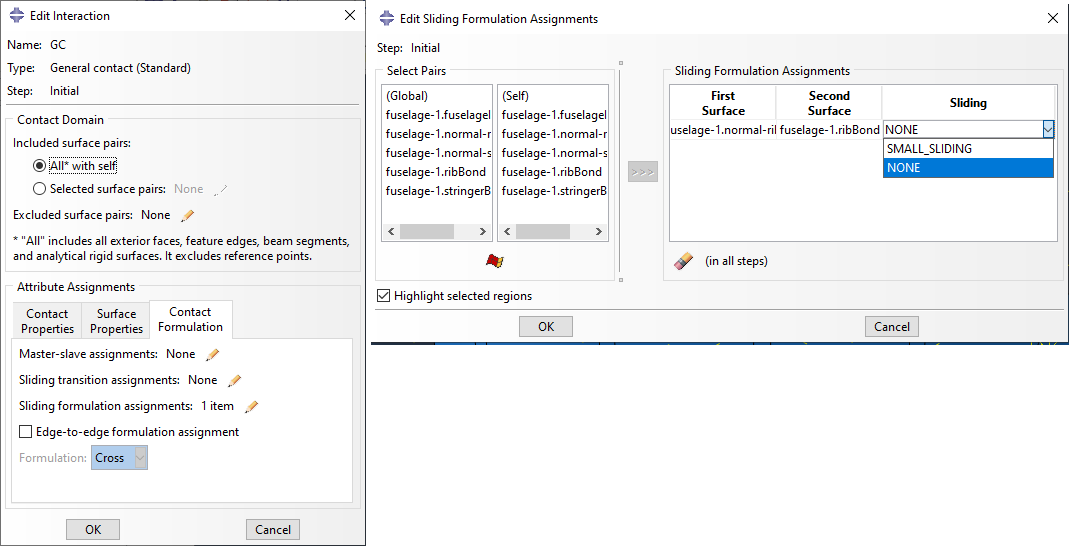
The small sliding formulation has been added, for general contact in Abaqus standard. This type of formulation can provide speed up in contact problems, when certain (strict) requirements exist between contacting surfaces.
A detail of this new implementation is given in Figure 2, below:

Figure 2: small sliding formulation in General Contact (Standard).
Trim Line Simulation for Sheet Metal Forming (Standard/Fd03)
The user can now perform a one-step inverse analysis.
This will allow for obtaining the initial shape of a sheet metal part, starting from its final (deformed) configuration. A reference surface is also required, to which the initial configuration(initial part shape) must conform. This functionality is suitable for flange unfolding applications.
This one step inverse analysis, focuses on predicting the unfolded geometry as well as trim lines. Additionally the user can attain stress/plastic strain results (for proportional loading) without actually simulating the sheet metal process.
This procedure is only supported for shell elements and needs to be set up via keywords (not supported in the CAE).
larc05 Damage Initiation Criterion
The LaRC05 damage initiation criterion used for polymer matrix composites, is the product of the efforts of the engineering community, as part of the WorldWide Failure Exercise (WWF-II). The philosophy of those efforts,is that failure criteria should take into consideration the physics at microscale level as much as possible, while also being able to provide failure indices at lamina/laminate level. Thus, the LaRC05 criterion, does provide high fidelity for assessing composite failure, while considering factors, at smaller scales. This useful criterion was previously available to Abaqus users, as a user subroutine, and supported solid continuum elements. The remainder of the Abaqus ply failure criteria, whether those were purely post processing failure envelopes (i.e. first ply failure criteria) or Hashin damage, were implemented for plane stress formulations (not to be used with solid continuum elements)
This new LaRC05 built in implementation in Abaqus, provides the user with a sophisticated failure initiation criterion, for three-dimensional solid, plane stress, shell, solid shell, and membrane elements.
When LaRC05 is used with default elements, then it acts a first ply failure criterion (cannot be combined with failure evolution-purely post processing).
The LaRC05 is supported for enriched elements (XFEM). In such a case, this criterion can be combined with failure evolution.
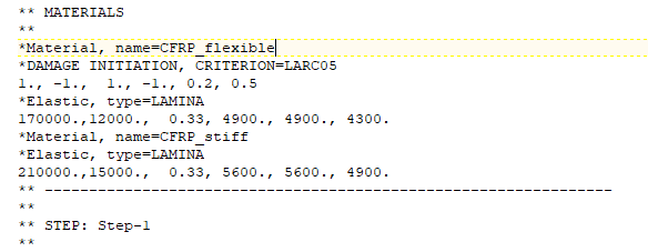
This failure initiation criterion is only supported via keywords (see figure 3).

Figure 3:LaRC05 failure criterion definition for composites analysis
More information about LaRC05 can be found in the documentation.
XFEM Accuracy and Robustness Enhancements
Significant effort has been put into improving the accuracy and robustness of XFEM.Improvements have been made for predicting crack propagation in 2D as well as with handling unstable crack growth.
Personally, I consider that the most valuable improvement, is the treatment of cracks in enrichment zones.
This is shown graphically in Figure 4, below.
In the past, only one crack was allowed to initiate in a single enriched zone. Additional cracks would not nucleate until all pre-existing cracks had propagated through the boundaries of the enriched zone.
If several crack were to nucleate sequentially, multiple enriched zones would have to be defined. This is demonstrated graphically on the left side of Figure 4. Such treatment of cracks in the past, increased the preprocessing times significanlty, particularly in cases were multiple cracks were expected in different plies.
In Abaqus 2021x, crack nucleation/propagation is treated differently. This is shown on the right side of Figure 5.
Specifically, within an enrichment zone, new cracks can nucleate irrespectively of pre-existing or active cracks. The candidate regions for crack nucleations, need only be outside a certain radius, from the active crack tip. This radius essentially defines a crack initiation suppresion zone around an active crack, and can be modified.

Figure 4: XFEM multiple cracks in single enrichment zone.
Other improvements include:
CAE
- For the SOLIDWORKS Associative Interface for Abaqus/CAE.
You can choose to export each body of a multibody part as a separate part in Abaqus/CAE.
You can choose to maintain all region boundaries on parts exported to Abaqus/CAE.
Abaqus/CAE considers the current assembly configuration in SOLIDWORKS when updating the model.
- For node-based submodeling, you can specify intersection only in the submodel boundary condition so that Abaqus ignores driven nodes found to lie outside the region of elements of the global model.
Analysis procedures
- Multiple nonlinear load case analysis
- Secondary base motion in modal transient and steady-state dynamic procedures
- Trim line simulation for sheet metal forming in Abaqus/Standard
- New GPU acceleration of the AMS eigensolver on Windows
- Iterative linear equation solver enhancements
Analysis techniques
- Adjoint sensitivities in a transient dynamic analysis
- Import enhancements
- Importing external fields in a sequential analysis
- Optimization enhancements in Abaqus/CAE
- Enhanced contact formulation for Eulerian analyses
- Special-purpose techniques for additive manufacturing
Materials
- Enhanced modeling of short-fiber reinforced composites
- User control of shell element transverse shear stiffness in conjunction with user materials
- LaRC05 and Hosford-Coulomb damage initiation criteria
- Metallurgical phase transformation
- Material enhancements in Abaqus/CAE
Elements
- Meshed composite beam cross-section enhancements
- Enhancements to general beam sections
- C3D10 element distortion control
- Enhancements to composites modeling with solid elements.
Contact and Constraints
- Enhanced hard contact for general contact in Abaqus/Explicit
- Defining initial conditions by importing results data from an output database file
- Enhanced rotational constraint for distributing coupling
- Evolving feature edge criteria with default angle thresholds
- Enhancements for general contact in Abaqus/CAE
- Enhancements for mechanical contact properties in Abaqus/CAE
A complete list of the enhancements together with a detailed description, can be found in the Abaqus release notes. You can download the software at software.3ds.com (with your DSpassport login credentials)


