

Posted by Christine Obbink-Huizer
Table of contents
In Abaqus there is a direct relationship between geometry and the final meshed shape: if we want to defeature or do an axisymmetric analysis, the geometry needs to be modified*. On the 3DEXPERIENCE platform, this is not the case. The geometry can remain unchanged. One or more abstraction shapes can be connected to the geometry, to represent simplified geometry. In this blog I will show this process for a bolt-and-nut assembly. We will have an axisymmetric model and 3D model based on the same geometry.
*An exception to this is the use of virtual topology. This allows small differences between mesh and geometry, by ignoring entities. This way you do not force the mesh to create element edges along all geometrical edges.
Geometry Import
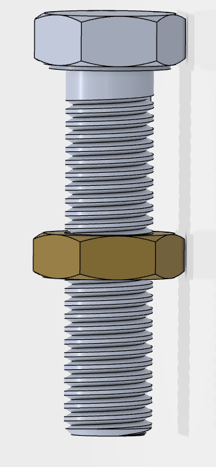
First the geometry is imported. In this case a SolidWorks Assembly from grabCAD.com is used.
Preparation
The Assembly Design App allows the user to do the things that are typically done in the assembly module in Abaqus, such as positioning, creating datum features, etc. This app is selected and used to create a plane and line that will be used to define the axisymmetric model later on.
Create FEM Rep’s
When switching to the Model Assembly Design app, there is an ‘automated FEM’ option. This will be used to create the axisymmetric model.
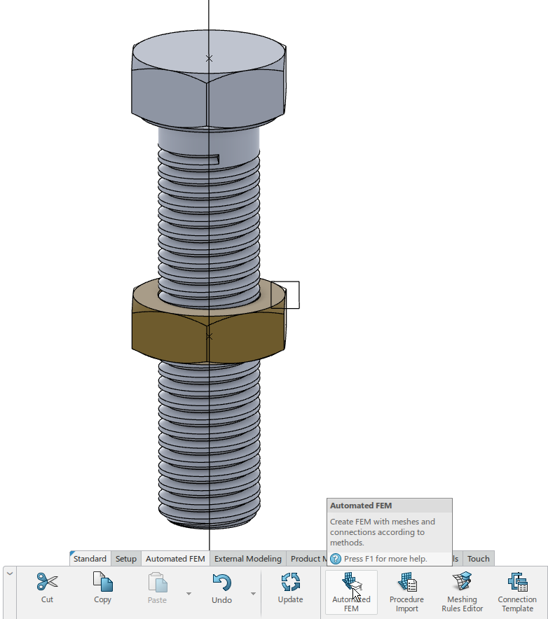
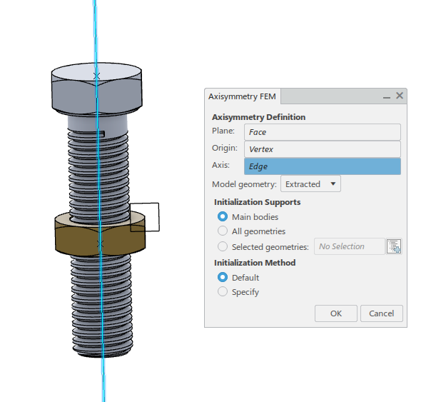
Using the automated FEM icon, from the Specialized section we select ‘Axisymmetric’:
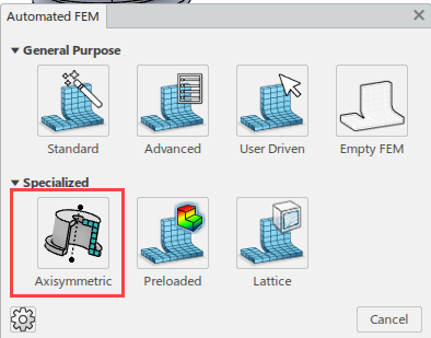
We then need to define a plane, origin and axis, and select the supports and initialization method.
The system then automatically creates a FEM Rep (indicated as Finite Element Model in the model tree by default) and an abstraction shape. These can be renamed for clarity, which is done here.
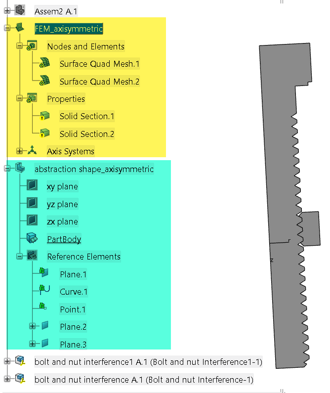
The FEM Rep automatically contains mesh and section definitions. These can be modified and/or extended as needed. Material properties need to be added in any case. Steel material properties are used here.
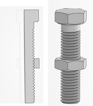
The abstraction shape is connected to the original geometry, but does not modify it. This way the original geometry is still available (for example to create a 3D FEM Rep), while the simplified geometry can be used for the analysis.
A second FEM Rep is made in the same manner. Double-clicking on the physical product at the top of the tree brings us back to the model assembly design app. From there, we can go use Automated FEM again, now using a standard automated FEM. With the default settings, the result is shown below. Manual adjustments can of course be made, and material properties have to be added. Here, the mesh is further refined to make is usable. The same steel properties as before are used.
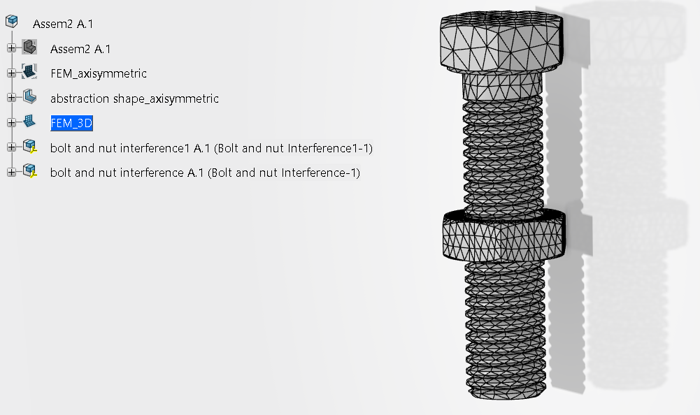
Both FEM Reps are then available in the same tree, as they represent the same physical product.
Analysis Cases
Once the FEM Reps are created, we can switch to the Mechanical Scenario Creation app.
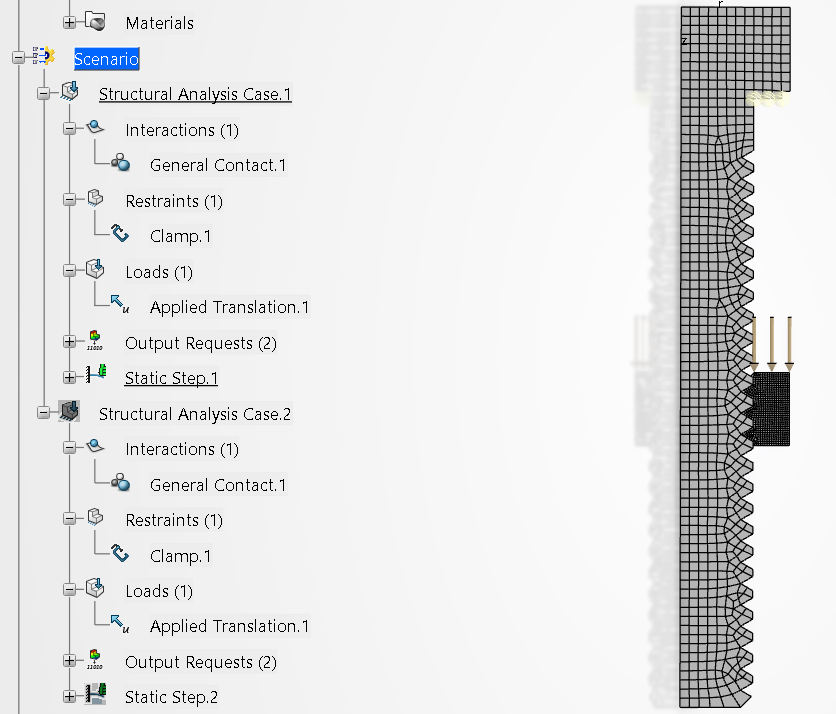
After specifying a name for the analysis, it’s contents can be defined. First a structural analysis case is defined. The FEM Rep that is to be used is selected. In this case we choose the axisymmetric FEM Rep. A static step is defined, and the simulation conditions are defined: a clamp on the inside of the head of the bolt, a displacement on the top of the nut and general contact with default (frictionless) properties. This is run.
A second structural analysis case is then defined using the 3D FEM rep. Equivalent simulation conditions are prescribed.
We now see both analysis cases in the model tree under Scenario.
Run Analyses
When clicking on ‘simulate’, the system lets us choose which analysis case to run. It is possible to select one, or run both at the same time.
If one analysis has completed and no changes have been made, then it is not possible to run it again. If changes have been made you can choose whether or not to save the previous version. Monitor information is available, similar to what is available in Abaqus.
Results
Once the analyses have completed, the results become available.
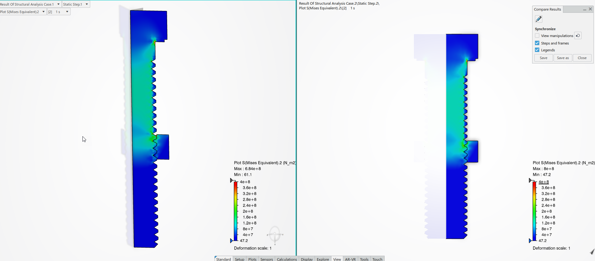
Different viewing options are available, including the option to compare two results. When only the prescribed downwards movement is allowed at the top surface of the nut (other displacement is restricted) then the results in the axisymmetric (left) and 3D model (right) match, for both axial displacements (top) and stress (bottom).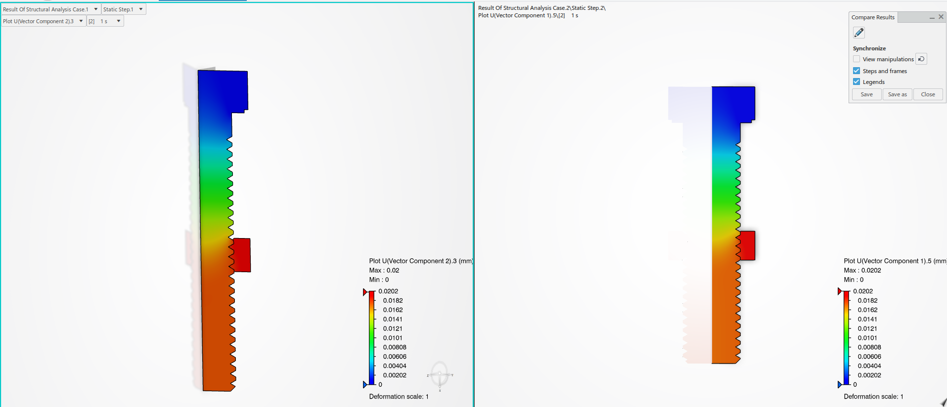
If the downwards movement is prescribed and displacement in other directions is free (no restriction), then there is a big difference between both models. In the axisymmetric model (left) the bolt is elongated, while in the 3D model (right) the nut rotates around the bolt, so the bolt does not displace: 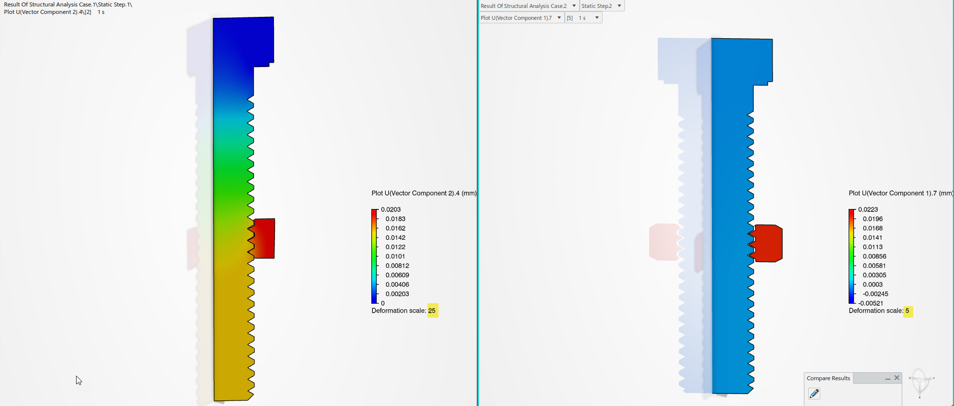
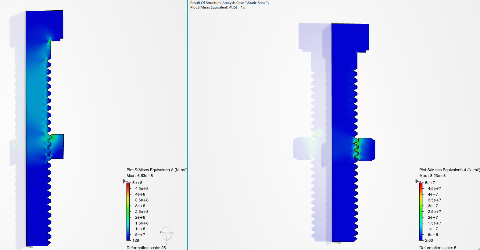
Because of this different behaviour, stresses are much larger in the axisymmetric model (left, maximal stress in legend 5e8), than in the 3D model (right, maximal stress in legend 5e7).
It therefore depends on the loading conditions whether an axisymmetric approach is reasonable or not.
Conclusion
The 3DEXPERIENCE platform offers a user-friendly tool to create axisymmetric models. Multiple finite element model representations (FEM Reps) can be linked to one physical product. This preserves the connection; it is always clear what geometry was used, and how it was derived. A physics simulation can contain multiple analysis cases, that can use different FEM Reps. This is handy when first doing a simplified axisymmetric analysis, and later doing a more complex 3D analysis or when varifying the assumption of axisymmetry.

TECHNIA Simulation provides top tier FEA, Non-linear, and Advanced Simulation Software, Training, and Consultancy. Our dedicated team of more than 65 Simulation experts across 16 countries advise and support your innovation with a wealth of specialist knowledge and experience.
About TECHNIA- Related news and articles straight to your inbox
- Hints, tips & how-tos
- Thought leadership articles

Helping you find the information you’re looking for. Discover webinars, events, FAQ's, case studies and tutorials.
VIEW HUB