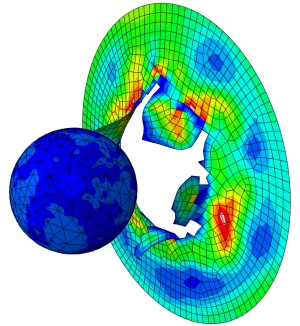
In this blog we have given the honour to Per Landeback as a special guest writer for our blog. Per has written this great blog about a parametrical Equation to calculate Rolling Resistance of a car tire.
Introduction
During my years of testing and simulation of various vehicles (Car, Bus, Truck and Train), I have been interested in how to describe rolling resistance of a wheel and read many published reports. Since the 1970 the number of published papers regarding rolling resistance has increased with a factor of 400. The published papers range from simple equations to complicated model.
A general parametrical equation that takes in consideration of the most important parameters is needed to be used as analytical or input to tire models. FTIRE measurements model used in several simulation programs (ex. Msc Adams), show poor representation of rolling resistance. Other tire models like PAC2002, which can be setup to function similar good as a FTIRE model, needs proper data to function.
I will here present a general parametrical equation that covers all needed parameters and show good fit to measured tire data. But before showing this, I would like to describe what rolling resistance is.
What is rolling resistance?
The primary function of a tire is to provide an interface between the vehicle and the road. Several forces resist movement of the vehicle; rolling resistance forces from the tire itself, aerodynamic forces, internal vehicle frictional forces, gravitational forces when driving up a slope and inertial forces when accelerating/braking.
The tire rolling resistance depends of three main causes; bending before and after contact zone,
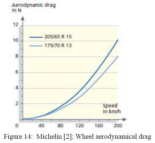
compressing and shearing in contact zone (80-95 %), micro slippage of tire to road (less than 5 %) and aerodynamical drag due to the rotating tire function as fan resisting motion (0-15%), see figure below. The aerodynamical drag varies with size of tire width and radius and is an almost square of velocity function.
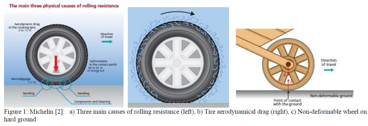
The most important cause of rolling resistance is the tire energy loss with temperature increase. While this is most affected by the visco-elastic material energy loss, also the stiffness plays a role by determine the area of the contact zone. To visualize this, figure 1c shows a rigid wood wheel. As can be seen, the contact area only consists of a point with no energy loss. This wheel will have zero rolling resistance, but horrible riding comfort.
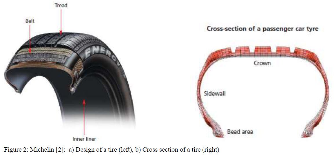
In a normal car/truck tire, the crown contributes with 70% of the energy losses, while the sidewalls and bead area 15% each. The crown is designed as a composite structure with a central metal belt and two layers of visco-elastic material (inner liner and tread), see figure 2.
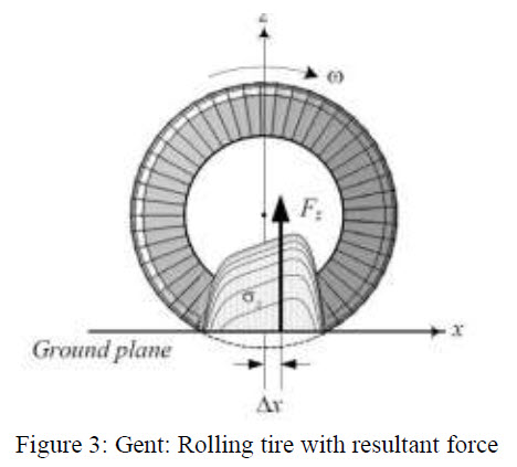
The energy losses in a tire comes hysteresis when the composite material (rubber and more) is
compressed/sheared and bended during rolling. A resultant force will be located slightly front of tire center as shown in figure 3.
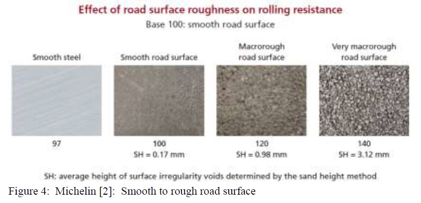
The surface of the road has an effect on the rolling resistance. A rough road surface has 40% more resistance than a smooth highway, figure 4.
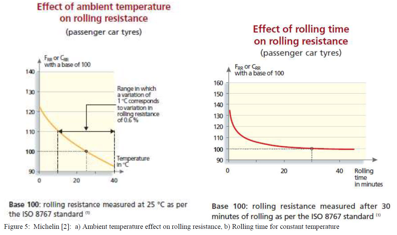
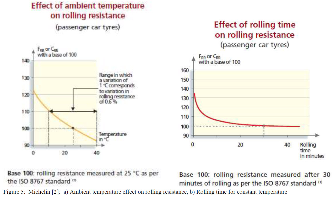
A very important factor is the ambient temperature and the created temperature in the tire. A tire works between 20 to 60 degrees C depending on tire type, type of driving and ambient temperature. If ambient temperature increase, the rolling resistance decrease. It takes about 30 min for a car tire to come to stable temperature and up to 3 hours for a bus/truck tire. According to ISO 8767 a tire should be run about 20 min before every measured speed.
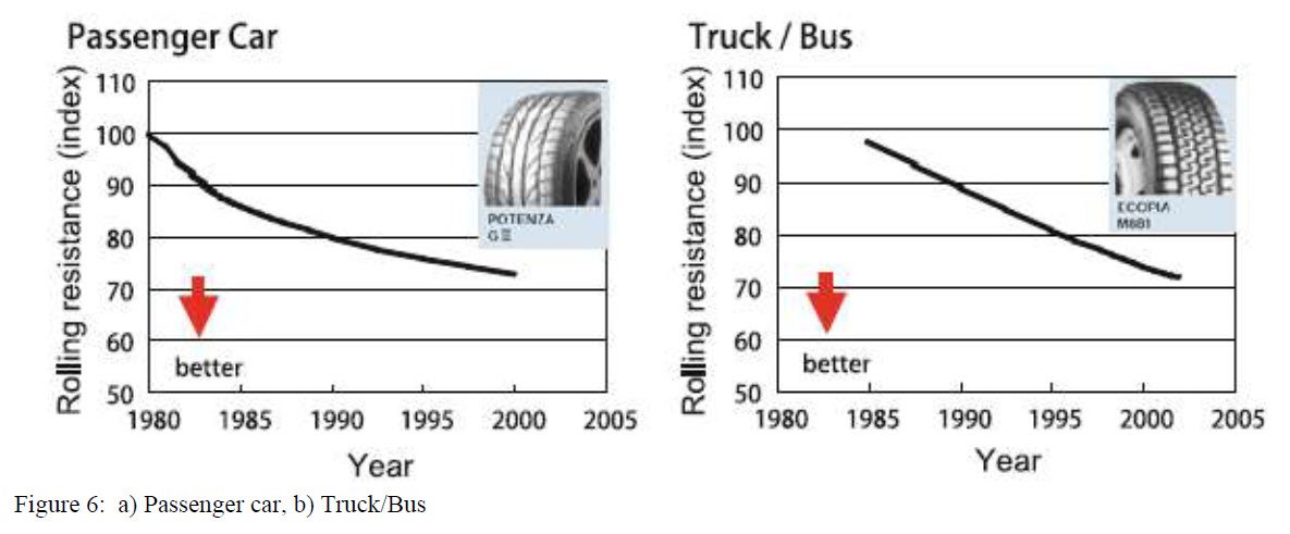
Continuous development of tire manufactures has lowered the rolling resistance and are coming to a level asymptotic level as can be seen in figure 6 [D.E. Hall, J.C. Moreland, Fundamentals of rolling resistance].
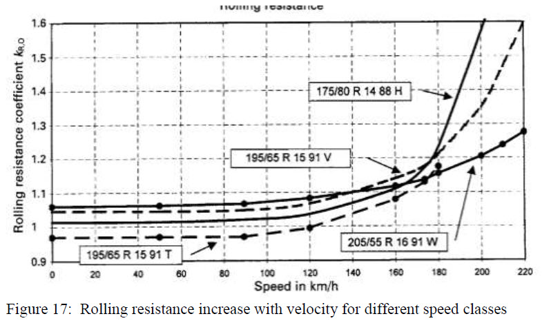
On top of all this there are different speed classes, like for car: S (180 km/h), T (190 km/h), U (200 km/h), H (210 km/h), V (240 km/h), W (270 km/h) and Y (300 km/h). The composite material of these speed classes tires is slightly different. The higher speed classes usually have more rolling resistance.
How is rolling resistance measured?
Four common methods are used to measure rolling resistance;
• Force on tire axle
• Torque applied on drum shaft
• Motor power
• Coast down (down rolling)
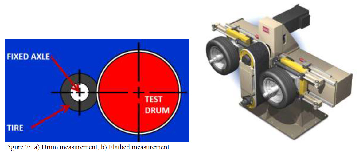
The drum measurements are the most common and has to be adjusted to get similar values as a flatbed measurement.
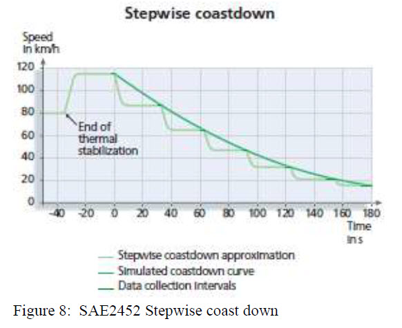
Different standards are used, in Europe mostly ISO8767 for car tires and ISO9948 for truck/Bus tires. US manufactures comply to two SAE standards; SAE1269 (drum test) and SAE2452 (stepwise coast down).
The easiest method is the coast down. If a stepwise is performed, the temperature is stable at each interval of speed. A continuous coast down will have slightly high temperature at lower speeds. Normally, the resistive force is measured at tire spindle, however if anyone want to do some investigations (private or professional), I will present some useful equations here.
Coast down analyze method:
Define Aerodynamical forces, eventually frictional forces (engine friction, wheel bearing friction and rolling resistance. The aerodynamical drag is defined as in equation 1 below. For a car, CD is usually around 0.3 and area is usual about 2.0-2.5 m^2. CD and these two are often treated as one constant together.

Rolling resistance as presented further down.
To calculate deceleration and velocity change, the effective rolling radius must be determined. Either use equation presented here or define a PAC2002 model. The presented equations are coming from various sources and are slightly changed or developed.
To calculate the effective rolling radius is needed the tire static stiffness. There are some variants of equations for this. Here is adopted this version:
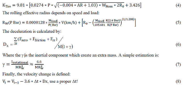
There is a problem with this method; there will be a deceleration for a car about 0- to 0.4 m/s^2, average 0.2 m/s^2 for coast from 100 km/h. This will have a slight increasing effect on the rolling resistance, but also slight too high temperature at lower velocities will decrease the rolling resistance.
The friction resistance forces due to bearings and more can be separately determined by use of a hard wheel or overinflated tire (asymptotic value) and coast down from lower speeds to zero.
Parametrical Rolling Resistance Equation
This general parametrical equation has been stepwise developed during years. The last version presented here, is updated this year 2021.
The rolling resistance has a direct relation to unloaded radius, tire width, pressure, load and velocity. Furthermore, is dependent on speed classes (different composite), essentially stiffness on the belt.
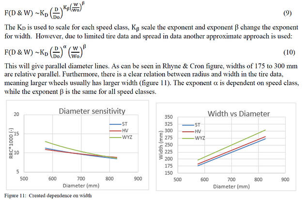
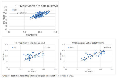
RR vs speed classes, radius and width Larger radius and width give lower rolling resistance, which is proved by several published papers. Furthermore, tires in different speed classes have a direct effect on the rolling resistance. The speed class ST (180-190 km/h) are slightly lower than speed class HV (210-240 km/h), while speed class WYZ (240-300 km/h) has more rolling resistance. This is due to the design demands and choice of composite material.
A large number of tires in three speed classes are measured according to standard SAE J1269. The standard prescribes 80 km/h with 80% load and corresponding manufacturer pressure. Due to that, slightly different loads and pressure are in these data.
The width has a direct effect on diameter power exponent shown by reference [7], so that small narrow tires give more rolling resistance (figure 9).
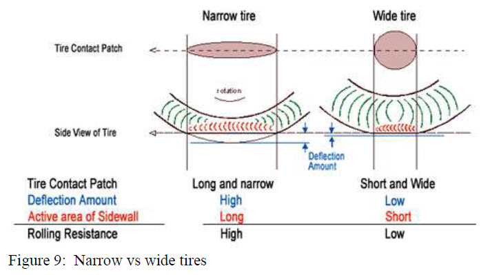
As shown in picture 9, width effect the rolling resistance, but in combination with radius. Rhyne & Cron
[7] limited and simple simulations show a direct relation between diameter and width. The used tire data have large noise due to slightly different load and pressure and only the RRC vs diameter can be determined. Dependence on width has been separately estimated.
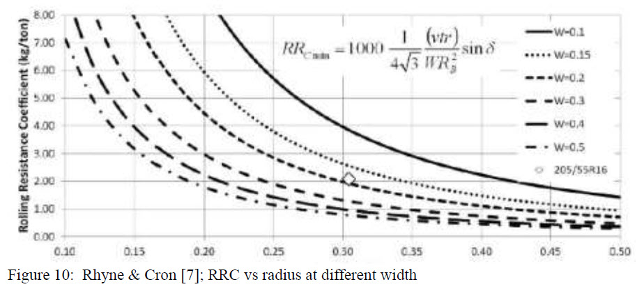
If a relation between diameter and width as shown by Rhyne & Cron could be proved, the equation would be:
RR force and RR coefficient versus pressure and load, quasistatic
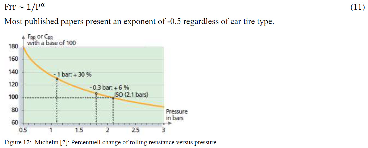
Quasistatic rolling resistance due to pressure and load. Rolling resistance increases rapidly as the pressure decrease. The reason is that lower pressure reduces tread blocks compression, but increase footprint and the tread block bending and shearing. The rolling resistance is therefore inverse dependent on pressure.
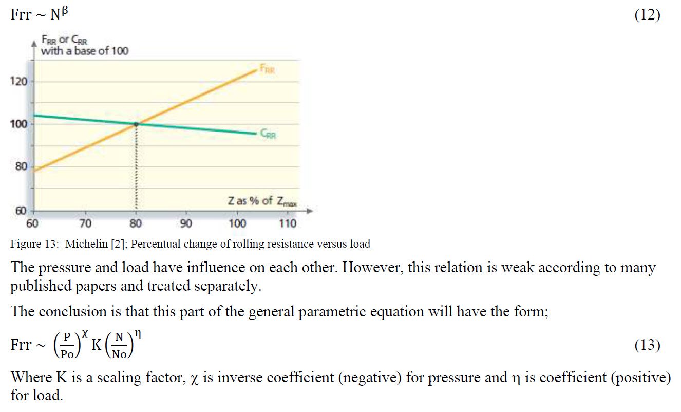
Rolling resistance force increase almost linear with increased load, while the rolling resistance coefficient typical decrease with increased load. The reason for is that increased load decrease viscoelasticity with increased temperature (more load) and create more bending and shearing. Many published papers treat the relation rolling resistance vs load as linear while Michelin report a weak non linearity with an exponent of 0.85. In figure 13 is shown the Michelin generalized behavior of increased load.
This description is only quasistatic and dependence on velocity will be treated separately.
RR force and RR coefficient versus velocity
Increased of velocity will increase the rolling resistance. There are several reasons, however the
dominating is change in viscoelasticity properties due to increased temperature with speed and
aerodynamical drag around the wheel (described above).
It is assumed that only the dominating parameters as pressure and load will affect the rolling resistance increase with speed. Larger radius and width will have slightly more rolling resistance due to increased aerodynamical drag, see figure 14. For simplicity, this is neglected in the rolling resistance parametrical equation. Other parameters like radius and width effect on increased speed are assumed to be small and are neglected (only influence on quasistatic).
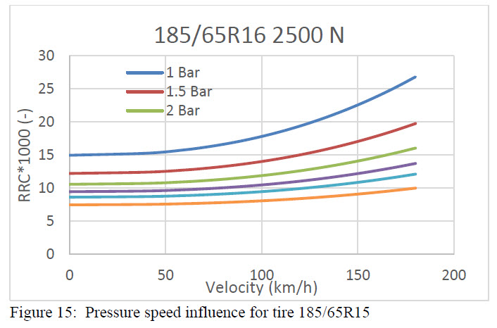
The pressure has a direct influence when velocity increase. Different tire size may influence, however there are few published papers about this. In order to make it simple, but still have an effect of this, the data presented in reference [10] are used to scale accordingly for change in pressure. In figure 15 is shown the pressure influence for a 185/65R15 tire (reference tire).
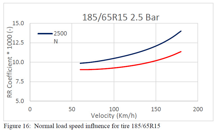
More load effect the velocity component. More load lowers the rolling resistance coefficient, but increase the total resistance force (slightly smaller coefficient multiplicated with a greater load). For a 185/65R15 car tire, with double load, the RRC is about 10 % lower at 80 km/h, but the force is 80% larger.
Furthermore, different speed classes will have an effect at higher speed, especially the WYZ speed class above 160 km/h. This effect of speed classes at larger speed is neglected.
This part of the parametrical rolling resistance regarding speed takes following form;

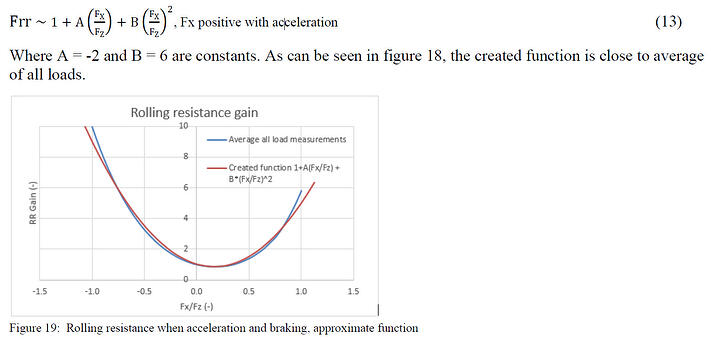
Rolling resistance when acceleration and braking
During acceleration and braking there will be additional deformation in the tire tread, which affect the rolling resistance. The generation of longitudinal forces is accompanied by some sliding in part of the contact zone. This means that more energy is lost and the rolling resistance coefficient will increase. This are very few published papers investigating this, one of them is reference [11]. The rolling resistance will have a minimum at a slight acceleration.
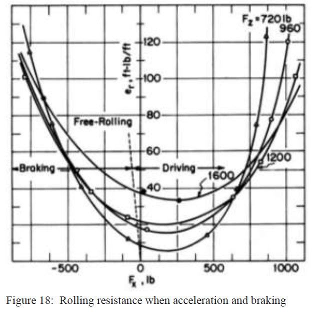
The load dependence is not very domination, so by creating gain of rolling resistance from zero
traction/braking, averaging for all load and create function vs Fx/Fz, this part of the parametrical rolling resistance takes the form;
The total parametrical rolling resistance equation
After going through all above the whole general equation can be designed. This equation is an analytical tool and will give reasonable approximate values of rolling resistance. The advantages are;
• Diameter effect on rolling resistance
• Width effect on rolling resistance
• Pressure effect on rolling resistance at quasistatic and dependence on velocity
• Normal load effect on rolling resistance at quasistatic and dependence on velocity
• Speed classes
• Braking and traction effect on rolling resistance
However, there are limits what a parametrical equation can do. The relation between radius and width can be affected by different viscoelastic properties and is not a guarantee the equation will give correct in some cases when extreme values, but a still a good estimate. Furthermore above 150 km/h some tires can have abrupt increase in rolling resistance.

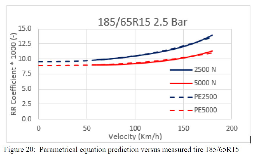
Where the constant KSPCL is the speed class factor. Reference tire is a measured 185/65R15 speed class ST (max 180 km/h). With set of all coefficient correctly a good match is achieved with measured values as seen in figure 19.
Using this equation for the different speed classes in the tire data base, a close match is achieved. The factors for different speed classes are estimated to ST 1.0, HV 1.08 and WYZ 1.165.
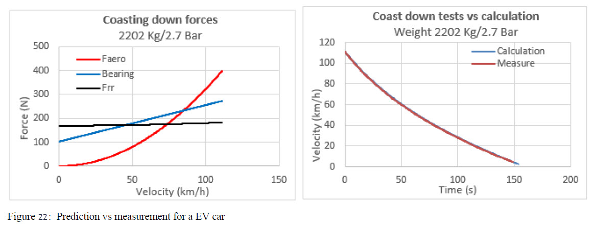
The rolling resistance calculator includes frictions in bearings, motor, wheels and aerodynamical resistance. The friction part is usually velocity dependent.
In a coast down measurement and using above equations, very good agreement is achieved for a EV car.
The friction part is estimated by using above general equation (an older version) and backwards estimation of the friction part, see figure 22.
Conclusion
The general parametrical rolling resistance equation can relatively well estimate the rolling resistance force for all car tires. Comparison to measurement, show a good agreement.
This parametrical rolling resistance equation can be used as input in tire models like PAC2002 or other. The general equation can also be used as an analytical tool for best choice of car tires. It can be possible to redesign the general equation for other tires like motorcycle and commercial heavy vehicle tire. Some constants and exponents may have to be changed.
References
1. Bharat Mohan Redrouthu Sidharth Das, “Tyre modelling for rolling resistance, division of vehicle
engineering and autonomous system, Chalmers University of Technology
2. Michelin, 2013, “The tyre Rolling resistance and fuel savings”, Société de Technologie Michelin
3. Ulf Sandberg, 2011, “Rolling Resistance– Basic information and state of the art of the art on
measurement methods”, Swedish National Road and Transport Research Institute (VTI)
4. F. Koutny, 2007, “Geometry and mechanics of pneumatic tyres”,
5. Ulrico Peckelsen, 2017, “Objective Tyre Development”, Karlsruher Institut für Technologie (KIT)
6. F. Koutny, “Geometry and mechanics of a pneumatic tires”, Zlín, CZE, 2007
7. T.B. Rhyne and S.M. Cron, 2012, “A study on minimum rolling resistance”, vol 40, Tire Science and
Technology
8. Yukio Nakajima, 2019, “Advanced Tire Mechanics”, Department of Mechanical Science and
Engineering, Kogakuin University, Japan
9. Alan N. Gent and Joseph D. Walter, 2005, “The pneumatic tire”, University of Akron, USA
10. Engineering Toolbox.com (https://www.engineeringtoolbox.com/rolling-friction-resistanced_
1303.html)
11. Samuel Kelly Clark, 1981, Mechanics of pneumatic tire, University of Michigan
12. Aug 2011, Special Report 286, Tires and Passenger Vehicle Fuel Economy,
http://onlinepubs.trb.org/onlinepubs/sr/SR286Rolling_Resistance_Data.pdf



 Retired test and simulation engineer with vast experience of various vehicles as car, bus, truck and train. Studied at Chalmers University of Technology and performed Master Thesis at a Volvo Aero military engine. Held previous positions as employee/consultant at SAAB, Volvo Truck, Volvo Bus, Bombardier, Scania Truck and NEVS (National Electric Vehicle Sweden). Technical aeras within Comfort, Handling, Braking, Steering, Suspension, Engine mountings, Tires and General component calculation/simulation


