
Posted by Philip Åstrand
Table of contents
Common challenging trade-offs bridge engineers face
Engineers often reinterpret the problems they are studying to find solutions using established theoretical methods. A significant part of their work involves finding an appropriate level of simplification, tailored to each specific project.
For bridge engineers, a common simplification is to model a bridge as a beam. While this approach is often useful and adequate, it requires awareness of its implications to make necessary adjustments during subsequent design steps, such as reinforcement design.
One major advantage of approximating a bridge as a beam - such as a concrete bridge - is the ability to use beam elements in Finite Element Analysis (FEA). This in turn means that the element output from the model (forces and moments) are in a format that can be directly used for reinforcement design, it is just a matter of combining the results according to the design code. It also simplifies comparative hand calculations using analytical methods.
However, there are limitations to this approach. Beam elements are one-dimensional structural representations, meaning they do not account for transversal effects. To address this, bridge engineers typically analyze the longitudinal response using the beam model and perform a separate analysis for the transverse behavior. While this method is sufficient in many cases, it may not be adequate for all scenarios.
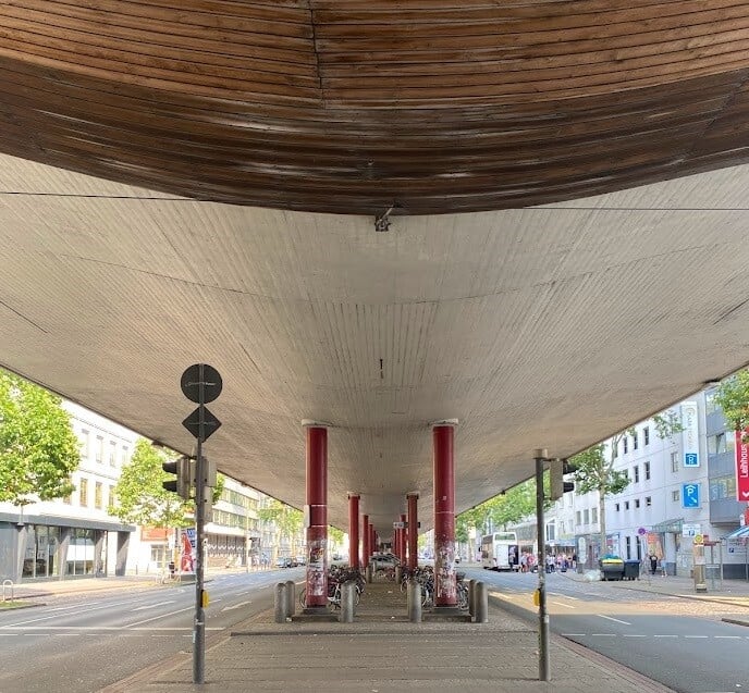
Breitenweg Bremen from 1968. Is it suitable to model the bridge deck as a beam?
In some cases, reducing a bridge structure to a beam equivalent is insufficient. A beam element in FEA assume that each cross-section is rigid and undeformable, an assumption that becomes less valid for wider bridges or those with complex cross-sectional geometry. Additionally, applying loads, such as traffic loads, becomes more challenging as the load bearing member increases in width. As the structural and loading complexities grow, 3D-effects become more significant, prompting bridge engineers to adopt shell elements instead of or in addition to beam elements. Shell elements allow for more accurate load application and directly provide element responses, including section moments and forces, which are essential for structural design of concrete members.
Shell elements offer the advantage of capturing significant 3D-effects and enable accurate analysis in both longitudinal and transversal directions within a single model, eliminating the need for separate calculations for the transverse load-bearing structure. Often, engineers use a combination of beam and shell elements to address varying structural needs.
However, as cross-sectional complexity increases, performing fundamental equilibrium checks - such as verifying total moment and shear force at critical cross-sections - becomes more challenging. These checks, straightforward for beam models, can be cumbersome when dealing with shell elements or mixed models of shell and beam elements, which are common in bridge design. With some effort, these checks can still be performed for basic load cases, such as dead weight.
As mentioned previously, bridges are also subjected to moving loads. In BRIGADE, a sophisticated approach based on influence lines and surfaces is used to calculate the response. In short, the most adverse response in each element or node is calculated by superimposing and combining response from individual actions by searching the influence response data.
When using a beam model, designing for responses from moving loads is straightforward as each position already represent the full cross-section, enabling design of critical sections directly. However, when the cross-section is modeled with shell elements or a combination of shell and beam elements, the analysis becomes more complex.
In these cases, each element in the cross-section may have its critical response - such as maximum bending moments or shear forces - originate from completely different load positions. For instance, the maximum shear force on the far right of the bridge is likely caused by the moving loads positioned on the far right, while the maximum shear on the far left arises when the load is positioned on the far left.
To determine the maximum shear force for the entire cross-section, simply summing the individual maximum forces from each element is incorrect because these forces might occur under different load positions. Instead, a more sophisticated approach is needed!
We need a solution which allows for analysis models composed of arbitrary element types to achieve accurate behavior of complex geometries but evaluates as simple beam models:
- fully considers 3D-effects
- single analysis model for calculation of design responses in all directions
- support for not only basic loads, but moving loads as well
- works for beam, shell, and solid elements
- provides integrated responses for entire multi-element cross-sections in a single output position
Let’s have a look at how this is solved in BRIGADE/Plus, using the Extended Free-Body Cut (FBC) functionality.
The extended FBC method: having the cake and eating it too
To understand what the Extended FBC Method does, let’s look at an example where a double box-girder bridge is modeled entirely with shell elements, to make sure that all 3D-effects are included in the model. With our solution, it is possible to get design results for the cantilevering parts in the transversal directions, direct in the global model.
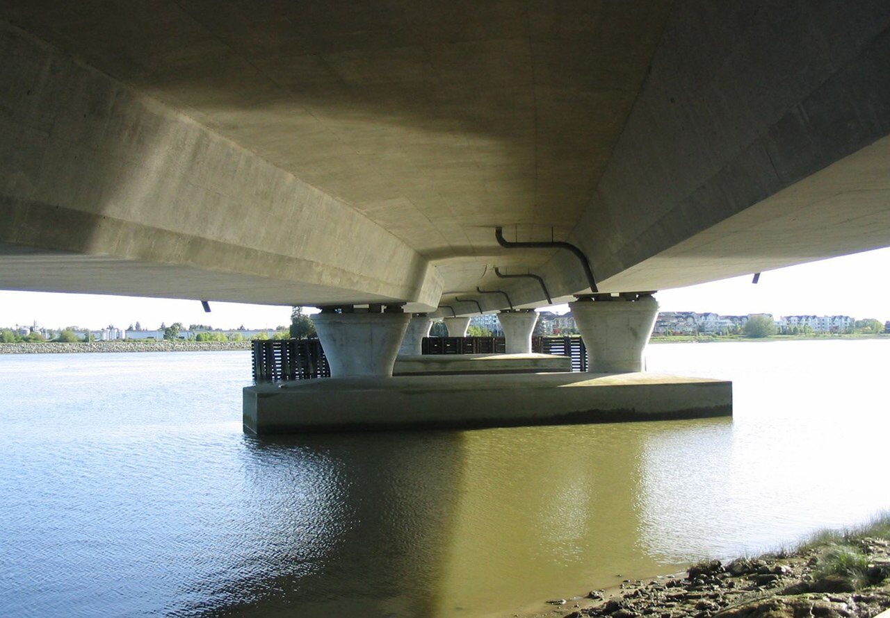
An example of this type of the bridge is the No. 2 Road Bridge in Richmond, British Columbia, Canada, although this example does note aspire to be an exact copy.
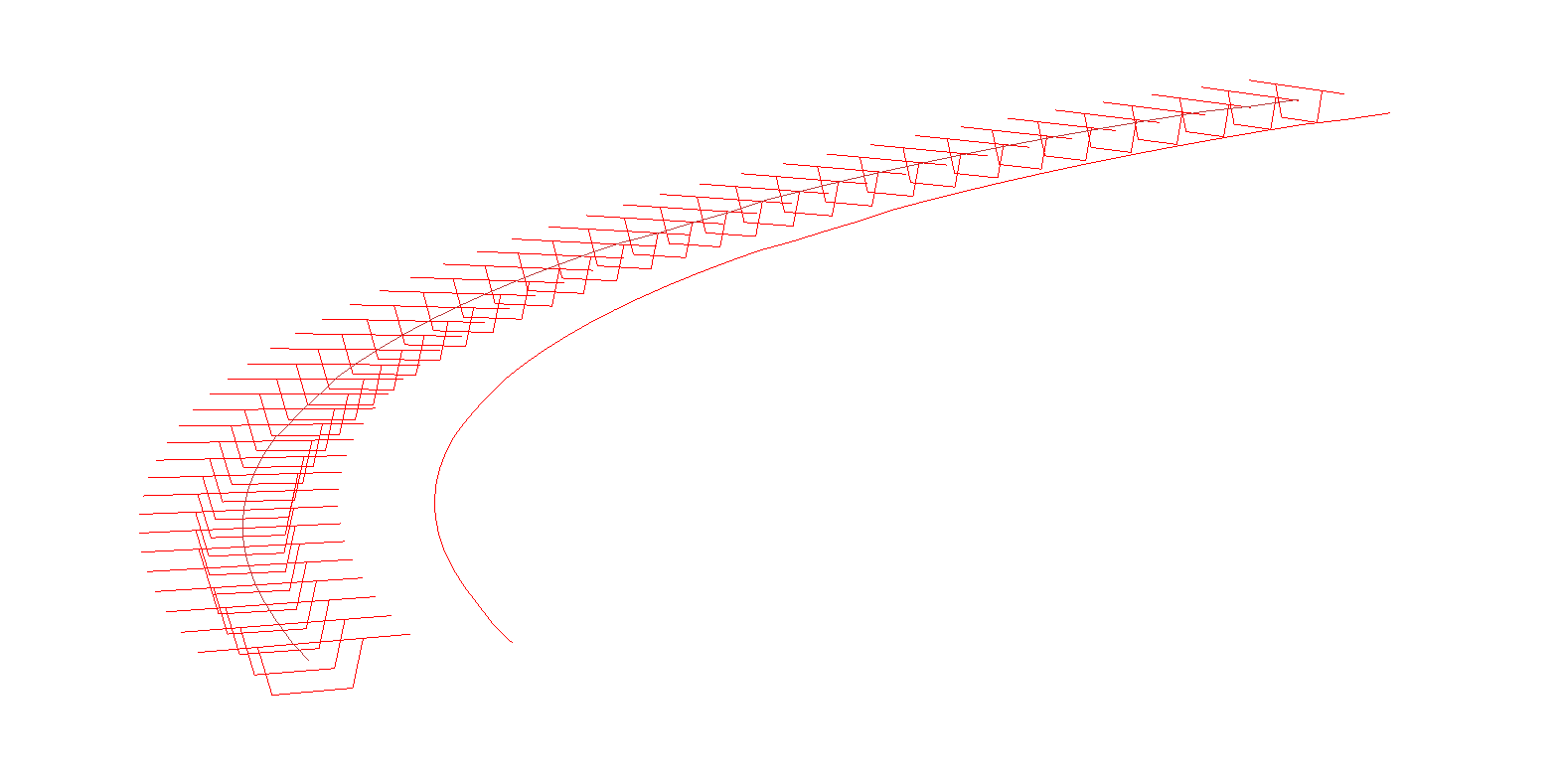
To utilize the Extended Free-Body Cut function in BRIGADE, several cross sections are defined along the stake out line in the modelling phase. For each of these user-defined cross sections, section moments and forces will be calculated. These outputs are unique output variables that BRIGADE calculate for each load case. The result for each section is then associated with a beam element positioned in the calculated center of gravity (COG) of each section respectively (the beam element itself is not included in the solver calculations).
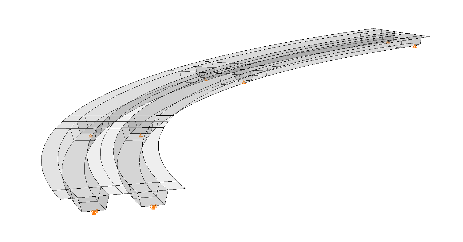
In the following image, the sections where output is requested are shown for one half of the bridge. For the other half, the output positions are displayed along the COG-line, where the results for each Free-Body-Cut section are written. This approach provides a clear visualization of the bridge’s structural response, combining the advantages of detailed shell modeling with the intuitive output of beam-model outputs.
For each applied load - including each individual traffic load position - results are calculated for each section output variable (SOF and SOM). These variables are analogous to the standard output variables for beam elements in BRIGADE (SF and SM). Since results are calculated for each section during every step of the solver-pipeline, the feature seamlessly supports the analysis of moving loads.
While the Free-Body-Cut (FBC) feature is also available in Abaqus, BRIGADE/Plus takes it a step further by extending the functionality to support moving loads. This makes the tool particularly valuable for bridge applications, where the analysis of live load effects is often critical.
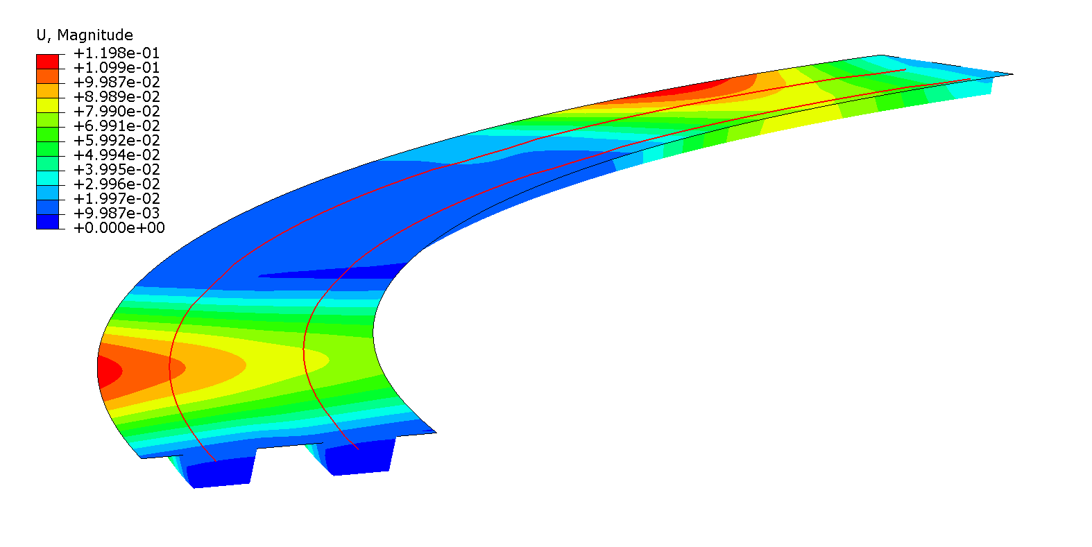
Deformation contour plot
When using the Extended FBC feature, the FEA-model can also produce the standard output results for shell and beam elements if requested. No request for Free-Body-Cut outputs are required, if there are valid section definitions in the model, BRIGADE will automatically produce the relevant outputs at each section.
When viewing the results, the user plots the results along the path/line that is associated with the sections.
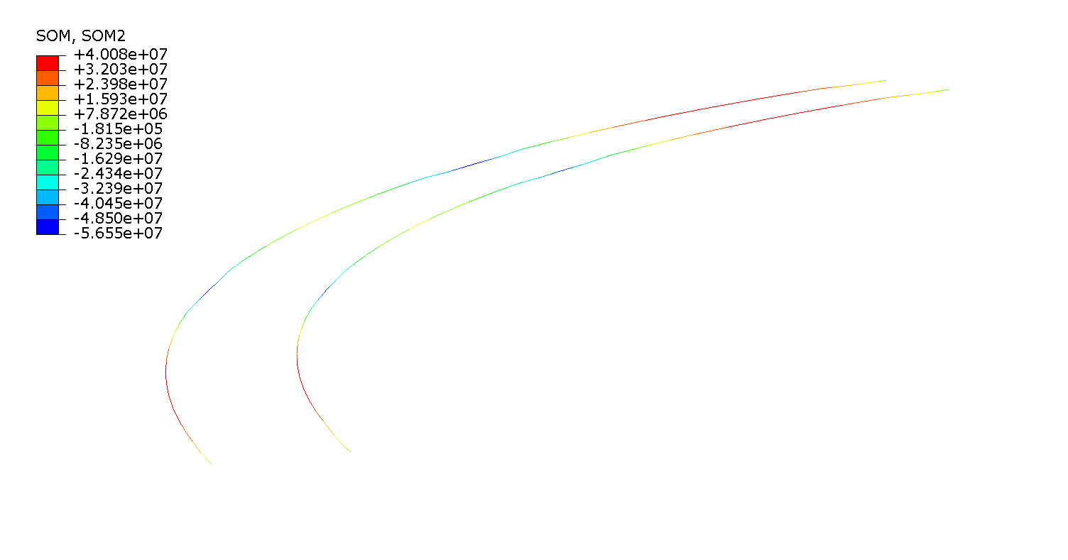
Moments along result lines for Dead weight load
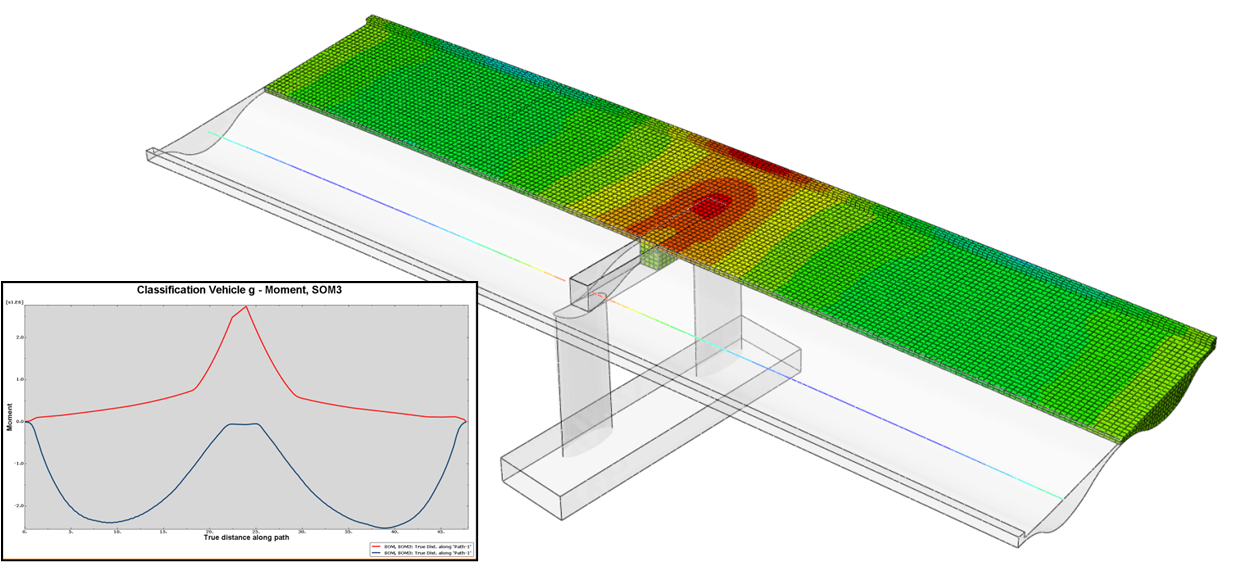
A typical use-case for a bridge engineer is to find the minimum and maximum moments and shear forces along the longitudinal stretch of the bridge. In the examples below, those outputs are plotted for one side of the double box-girder cross section of the example bridge. In this example, the results are plotted for a classification vehicle.

Min/max moments along the longitudinal direction of the bridge for classification vehicle.

Min and max shear force along the longitudinal direction of the bridge
Expanding the use of continuum/solid elements for structural verification
While continuum (or solid) element models excel at representing detailed stress distributions, they are rarely used for structural verification of concrete bridges. This is mostly due to their limitations in providing section forces required for conventional design according to common design codes. Our solution for Extended Free-Body-Cut (FBC) solves this - sometimes frustrating - gap in analytical capabilities.
Engineers traditionally rely on simplified models - beam or shell elements - for designing bridges. These models focus on section forces rather than stress distributions, which aligns with design codes.
Solid element models provide a more accurate representation of the structural behavior but only output stresses, which somehow must be translated into section forces. This conversion process often introduces significant conservatism, rendering the results impractical for precise engineering decisions.

Bridge modeled with solid elements and result extraction with Extended FBC

Visualization of critical traffic/live load position for an integrated cross-section from Extended FBC
Unlocking the future of bridge engineering
BRIGADE/Plus enables new ways for how engineers can calculate and design complex bridge structures. Our free-body diagram solution allows for extracting design-relevant section forces directly from detailed solid or shell element models, achieving a level of precision previously unattainable with conventional methods.
The Extended FBC method bridges the gap between conventional analysis approaches and the demands of modern bridge design. Its ability to extract design section forces and moments from detailed models ensures safety without conservatism. For bridge engineers, this means more reliable, efficient, and innovative designs.
Explore the potential of the Extended FBC solution in BRIGADE/Plus and elevate your bridge design capabilities. Contact the BRIGADE team at TECHNIA today to see how this advanced feature can transform your structural analysis and help you stay ahead in the ever-changing landscape of civil engineering.
Examples of projects where Extended FBC has been used
You are welcome to read our case study articles about Sweco and STING, both of which use Extended FBC in their bridge design projects.

TECHNIA Simulation provides top tier FEA, Non-linear, and Advanced Simulation Software, Training, and Consultancy. Our dedicated team of more than 65 Simulation experts across 16 countries advise and support your innovation with a wealth of specialist knowledge and experience.
About TECHNIA- Related news and articles straight to your inbox
- Hints, tips & how-tos
- Thought leadership articles

Helping you find the information you’re looking for. Discover webinars, events, FAQ's, case studies and tutorials.
VIEW HUB