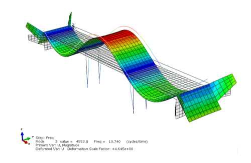
 Advanced Simulation

In this blog we will discuss the process to determine movement of bodies due to a fluid flow, performed with XFlow CFD. As an example we have taken a historic measurement device called a "Wildse Vaan".
Introduction of the "Wildse Vaan"
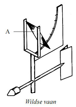
The Wildse Vaan is an old pressureplate anemometer, called after the inventor "Wild". In this device is a plate, with dimensions of 150 x 300 mm and a weight of 200 gram, hang up on a horizontal axis, that is placed perpendicular to a windvane or wind-direction indicator .
By doing so, the plate will always be positioned perpenducular to the wind drection. Along the plate is another arced plate with indications that are numbered from 1 till 8.
The angle which the plate will make under influence of the wind, is the measured indication for the windspeed. This principle of a pressure plate was already used in 1450 by the Italian Leon Battista Alberti. Leonardo da Vinci also experimented with the pressure plate between 1452-1519.
In 1860 the "wildse vaan" was positioned on a windvane to assure a better perpendicular position to the wind, and became officially recommended for use in Meteorology. Even till late 1950's this anemometer was still available from the German manufacturer Fuess.
| Pen number | Angle in Degr. | Wind speed in m/s | Beaufort |
| 1 | 0 | 0 | 0 |
| 2 | 4 | 2 | 2 |
| 3 | 15,5 | 4 | 3 |
| 4 | 31 | 6 | 4 |
| 5 | 45,5 | 8 | 5 |
| 6 | 58 | 10 | 6 |
| 7 | 72 | 14 | 7 |
| 8 | 80,5 | 20 | 9 |
The simulation 3D geometry model
The information and table above were translated to a 3D-CAD Model using SOLIDWORKS, and instead of numbering the pins, I have created cut-outs that show the windspeed in scale of beaufort (let's call it the "Broekaart" model 😜). Additionally I have added the windscale in m/s if you prefer that over BFT. This makes it a very simple model to "validate" your simulations or your rigid body dynamics settings in any CFD software.

If you are planning on making or 3D-printing this particular model in real life, just make sure that the plate has an exact weight of 200 grams for a surface of 150 x 300. For our simulation, the exact weight was set in XFlow CFD, instead of fiddling with densities or different thicknesses in SOLIDWORKS. We used a density of ~2223,5 kg/m3 to get close to the 200 gram plate for this modelled plate thickness.
The analysis setup process in XFlow CFD
Environment settings
It all starts with the setting of the desired windspeed condition. In this case we have chosen for a 7m/s windspeed, which is a solid 4 Beaufort. See table below:

Although quite neglible in this particular case, we have added gravity to the fluid media, by applying a -9.81 m/s2 in Y-direction. The domain is chosen to be not too big to reduce calculation time and amount of cells. All environment settings can be found below.

Material settings
When chosing a "virtual windtunnel" template in XFlow CFD, the defailt material or Fluid Media is Air:

Geometry settings
This is where we determine which parts need to be considered as fixed (for the vane itself), or if we apply rigid body dynamics (for the plate). Also we need to make sure that the weight of the plate is as sculpted before (200 gram).

Since XFlow automatically puts the center of gravity in the origin, we need to let the system calculate the center of gravity, particularly for the plate, as the origin is not in the CoG of the plate. We do that by right clicking on the plate, and pick: "Modify Cog/Cor position"
if you click on the center of gravity icon, the CoG will be recalculated an placed in the middle of the plate.

In this particular case, the Cog of the plate is not at the same location as where it would rotate. This can be enforced by using a hinge in the Rigid Body Dynamics settings. As we will use a hinge to define the rotation movement, we should allow all the movements under the rigid body dynamics to be considered as Free. Furthermore we need to make sure that the gravity forces are not only applied to the fluid, but also to the bodies. We do that by applying an External global force in the Y-direction of Gravity X mass. See all the settings below.

Last but not least, the hinge is created on the position of the rotation axis. 
Simulation settings
Under simulation settings we determine the desired total simulation time, and remember that XFlow is always transient. For this analysis we have chosen 2,5 seconds.and left the timestep to "fixed automatic".We did use an adaptive resolution approach, so that the cells represent the thin plate, and follow the moving geometry once it starts to rotate. Additionally to that we have used a refined region for the area behind the plate. see all settings below.

This will give the following cell distributions with 347774 cells in the total domain.

The results
Running this simulation an an average 3-year old office laptop with 4-Cores took approximately 17-hours. Accorrding to my angular movement graph, I could have reduced the total analysis time to 1,25 seconds, which would reduce the calculation time to a total of 8,5 hours.


In the zoomed image below, you can see that the plate indicates between 4 to 5 BFT and between 6 to 8 m/s. According to the Beaufort scale that is exactly where it should be for a given windspeed of 7m/s.

Additionally, we have setup a system with double rotation freedom. See the video below: