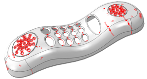
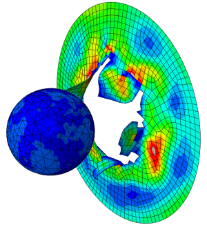
In this blog post, we will be discussing about geometry operations on 3d models, that have been imported in Abaqus as a neutral geometry format, or via the Associative Interface (if you are interested more about the AI, have a look at an earlier blogpost). We will be showing the different tools available in order to detect geometry issues in the imported model (Geometry diagnostics tool, accessible via the Query tool) as well as fix geometry issues from within Abaqus (Geometry Edit toolset, accessible through the Part module in Abaqus).
Introduction
Upon importing a part (solid, shell, or combination of both), Abaqus tries to create a closed part(solids) or a connected shell part (shells). If the import operation is successful, the part is considered valid and precise. If the precision of the original part (adjusted based on neutral format export settings in the CAD software) is less than the precision used by Abaqus, the part may be imprecise or invalid.
You can continue working with an imprecise part or even with an invalid part if you repair it or choose to ignore the invalid status.
Precision & Tolerance
Precision and tolerance are important considerations for successfully importing a part into Abaqus/CAE. For trimmed surfaces the tolerance defines the maximum allowable deviation between an edge and the surface bounded by the edge.
The accuracy of the polynomial defining an edge of a trimmed surface depends on the tolerance of the CAD software used. Abaqus/CAE uses ACIS to represent a part or the assembly. ACIS uses a precision of 10−6 to define a geometric entity.
Imprecise and Invalid Parts
A valid part can be either precise or imprecise. If Abaqus needs to use a looser tolerance (than the built in) in order to recreate a closed volume in some area, the part is considered imprecise.
You can continue working with an imprecise part. If Abaqus cannot continue, you should try and suppress the imprecise region, and using the geometry Edit toolset, try and turn the imprecise regions into precise ones. If the part contains complex surfaces, this operation may prove too time consuming. In a case like that, it might be more meaningful to return to the CAD software and increase the precision.
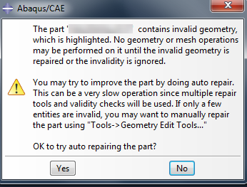
If the errors (due to tolerance differences between software, large gaps between edges etc), are so large, that Abaqus fails to create closed volumes/connected parts, the part will be considered invalid.
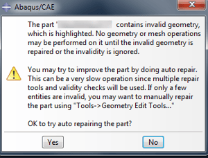
Figure 2: Invalid part dialog box.
You can proceed to work with the geometry edit toolset to try and validate the part. If the repair is not possible, you can either decide to ignore the invalidity (right click the invalid part on Model tree --> Ignore invalidity), or continue to use the part as if it was valid.
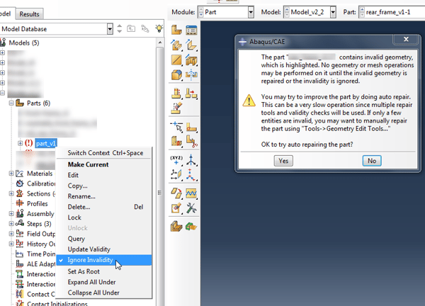
Figure 3: Ignore invalidity command.
However, unlike imprecise parts, operations invalid geometry may fail, cause instabilities or give inconsistent results. As good practice, fixing the invalid geometry should be primarily a task for the CAD software.
Geometry Diagnostics
The geometry diagnostics toolset, allows the user to diagnose potential issues with an imported geometry. This tool can be accessed through the Query tool in Abaqus, or via the File menu as shown in Figure 4.
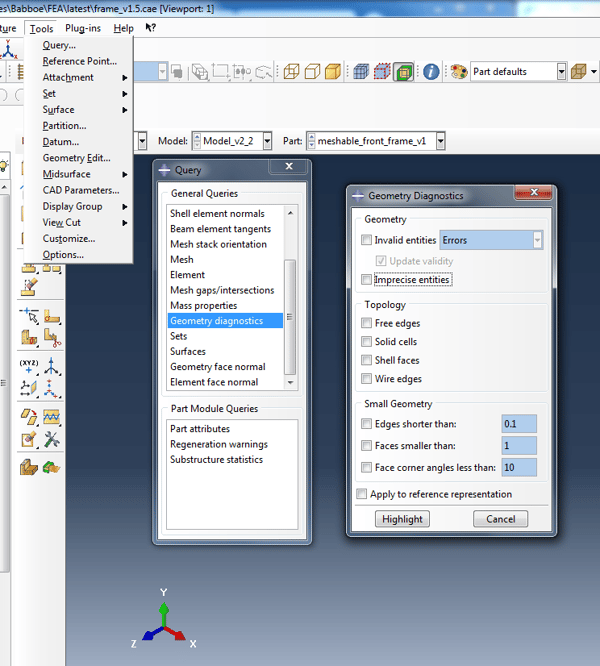
Figure 4: Geometry diagnostics tool.
- Invalid/Imprecise entities: Allows you to diagnose, invalid and/or imprecise entities, indicating the areas that require attention and correction.
- Free edges: Abaqus will highlight free edges including shell and wire edges. A solid part should not contain those.
- Solid cells: Abaqus highlights the solid cells of the part.
- Shell faces: Abaqus highlights the shell faces of a part.
- Wire edges: Abaqus highlights the wire edges of the part.
Small entities such as short edges, small faces but also faces with small face corner angles can affect the mesh quality. The last three options of the geometry diagnostics tool (edges shorter than, faces smaller than, face corner angles less than) are focused towards locating really small geometry features that are practically redundant and can affect the mesh quality.
Geometry Edit Toolset
All various features of the geometry edit toolset are shown in Figure 5. The geometry edit toolset is only accessible via the Part module.
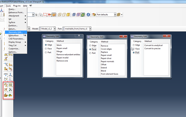
Figure 5: Geometry edit toolset.
Operations on Edges
- Stitch: If you import a part as a group of disconnected faces, by using the stitch command you can stitch the resulting small edge gaps. This operation can also be used, after having removed small faces or small slivers(really small faces, having unreasonably small areas).
- Repair small: You can repair selected small edges. Abaqus removes small edges and edits the adjoining edges to create a closed geometry.
- Merge : You can select a series of connected edges, and Abaqus will merge them while removing redundant vertices along those edges
- Remove redundant entities: Those entities can be vertices located along a continuous edge. This feature allows you to remove this entities.
Operations on Faces
- Remove: This feature allows you to remove selected faces (fillets, holes, chamfers) from a 3d solid or a shell.
- Cover edges: You can create a face on a 3d part by selecting one or more edges of the new face. Abaqus will loop through the adjacent edges and calculate the location of the new face.
- Replace: This tool is particularly useful in a case when a face, upon import, appears wavy or distorted. What effectively happens is that Abaqus creates and connects small faces instead of a single face. You can use this feature to replace the small faces with one face.
- Repair small: Allows you to repair small faces. Abaqus will then remove those faces and will edit the remaining faces to create a closed geometry.
- Repair sliver: A sliver can be thought of as a small sharp piece of extra material. This feature is used to remove this type of artefact from an imported geometry.
- Repair normals: You can repair the face normals for shells and solid elements. It is more rare to use this tool for solids, as Abaqus will recognize the solid's volume as negative (implying some insufficient or wrong modelling in the CAD software). For an imported shell, this tool becomes more meaningful, as there might be the case that normals of shells are facing in opposite directions.
- Offset: You can create faces on a 3d part by selecting the faces to be offset and then specifying an offset distance.
- Extend: You can extend existing faces by specifying an extension distance or selecting target faces to control the distance.
- Blend: You can create new faces that blend the contours of existing edges in a model to form fgaces between those edges.
- Face from element faces: You can create a new geometric face from orphan element faces. Abaqus creates a new geometric face based on the node positions of the selected element faces.
Operations on Parts
- Convert to analytical: Abaqus will try to change the internal definition of edges, faces and cells, into a simpler form that can be represented analytically. The advantages from that operation, are that you can process the part faster, the geometry is improved, and if you need to subsequently stitch the part, the stitching operation is more likely to be successful.
- Convert to precise: Two options are available here. Tighten gaps, will attempt and improve the precision of faces, edges and vertices in your model. This method is faster (compared to Recompute geometry) but does not perform a full geometry computation. Recompute geometry, will try and change adjacent entities so that their geometry will match exactly. This action usually results in precise geometry. However this operation based on the model size, can be lengthy, and it will also increase the complexity of the imported part. This means that processing times will be longer. Additionally if the part comprises from complex surfaces, the convert to precise operation will most likely fail.
Are you interested in learning more?

