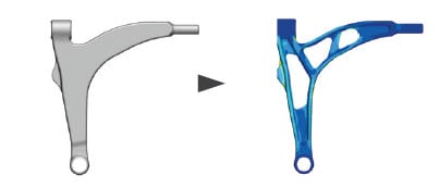
Tosca is used for non-parametric optimization. It has several different flavors; it can be used to determine:
- where to put a fixed amount of material in order to get the stiffest result (Tosca topology)
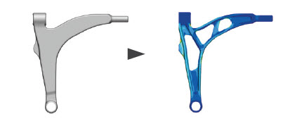
- where to place nodes on the outer surface to have a more even, and therefore lower stress (Tosca shape)
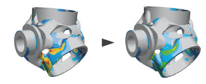
- where to place beads (Tosca bead) and
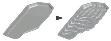
- how thick different shells should be (Tosca size).
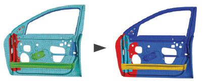
In this blog, we’ll look at a rather new flavor of Tosca: Tosca sizing for circular beams.
As an example, a truss construction will be used, inspired by the ones above the highway used to fix digital signs.
The geometry is shown below. Our goal will be to obtain a stiff structure, while limiting the weight of the material.
The general approach will be similar to the one discussed in a previous blog: an Abaqus model will be created first, and after this an optimization will be defined for this model. Both steps are performed from the same graphical user interface: Abaqus/CAE.
Abaqus Model
The Abaqus model is set-up as normal. The signs are discrete rigid bodies that are tied to the beams. One side is constrained, while symmetry conditions are applied to the other side. Gravitational loading is applied and an inertia is included for each of the signs. B31 beam elements are used, with a circular profile. This is important, because optimization is not possible with other profiles. All beams have the same radius initially. A test run is performed to ensure the model behaves as expected.
Objectives and Constraints
Once the model is set up, the Tosca sizing optimization is defined. This is done from Abaqus/CAE as well. We need to tell Tosca what an optimal solution is, by specifying an objective and constraints. The objective is something that should be minimized or maximized in the optimal solution, while constraints limit the allowable solutions. In this case the objective will be to minimize the displacement in vertical direction of the nodes at the symmetry condition, under a mass constraint. Without a constraint, the optimal solution is often to use as much material as possible. Because this is not very informative, usually a constraint needs to be applied.
Geometrical Restrictions
Once this is done, the basic (mathematical) model is defined. It could be run now, but the results obtained may be difficult to manufacture. Geometrical restrictions may aid in such a case. There are different options available, such as applying symmetry conditions or having frozen areas (regions that aren’t modified). In this case, we will apply two different types of geometric restrictions, and see how this influence results.
Case 1: Thickness Control
Thickness control allows the user to specify a range of allowable thickness. This can be specified either as values or as fraction. In this case we will specify fractions with a maximum of 5 and minimum of 0.2. This means that the final radii will be between 0.2 times the original radius and 5 times the original radius. With an initial radius of 20 mm throughout the model, final radii will be between 4 and 100 mm.
Case 2: Clusters
Unless specified otherwise, each element can have a different radius. This is often not practical. Therefore, clusters are created. All elements in a clusters will have the same radius in the optimization result. Clusters must be specified by the user. In this case, I have chosen the clusters in such a way, that repetitive units will arise. In the figure, each cluster has a different color.

Running the Optimization
After the appropriate optimization processes have been made, they can be run and the progress can be monitored. Around 15 runs of the Abaqus model are required. After the analysis is finished, results from all runs can be combined into a single .odb, to view how the optimization progressed.
Results
The following movie shows the element thicknesses (colors) for both cases during the optimization. Case 1 is on top, case 2 on the bottom. A scale factor of 50 is used for displacements. Note the different scales of the legends.
Images are shown below.
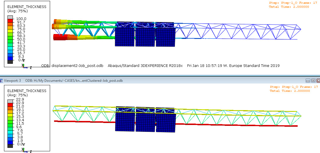
Element thickness in unclustered model (top) and clustered model (bottom). Note the different legend scales. A scale factor of 50 is used.
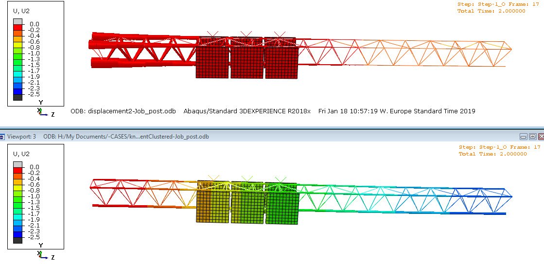
Displacement in vertical direction in unclustered model (top) and clustered model (bottom). The same scale is used for both legends. A scale factor of 50 is used.
Without including clusters, most material is placed near the constrained end. Differences between element radii are large: both the smallest and the largest radius that is allowed are used. This gives a maximal displacement of around 0.5.
With the clusters specified, the solution without clusters is not allowed. In this case, the horizontal beams are thickest. Of the three, the bottom is thickest. The maximal displacement is around 2. This is 4 times the maximal displacement without clusters. This exemplifies an effect seen in general: by including geometric restrictions, the amount of possible solutions is limited and therefore the optimal solution found becomes less optimal.
Conclusion
Tosca sizing can also be used to optimize the radius of circular beams. Geometric restrictions can be added to make the result of the optimization more easy to manufacture. In general, this comes at the expense of having a less optimal solution, as measured by the objective function.

