
Posted by Christine Obbink-Huizer
Table of contents
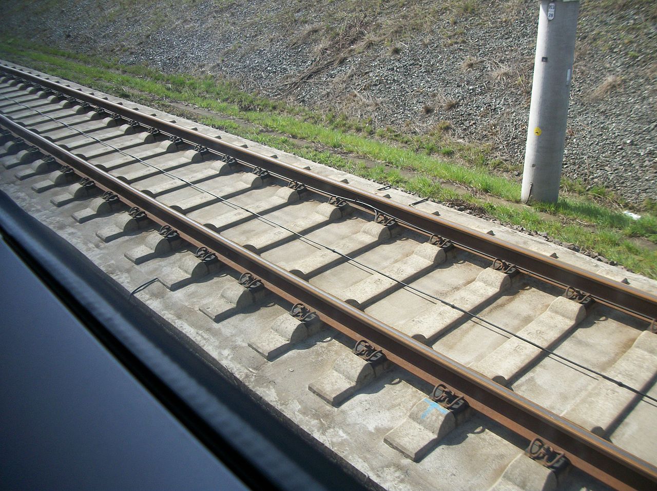
In the hot rolling process, metal is heated and passed through one or more sets of rollers, to give it the desired cross-section for example. This process is used for the fabrication on railway tracks (Figure 1).

Figure 1: Example of a railway track (By Photnart - Own work, CC0, https://commons.wikimedia.org/w/index.php?curid=26572319)
Twenty rolling operations may be used to obtain the final shape. In this blog, we will simulate part of this process, using Abaqus. A while back, we posted a blog on simulating roll forming in Abaqus. This was about sheet metal forming, where the sheet metal was described by shell elements. For the application in this blog, shell theory is not valid and solid elements will be used.
Geometry
The to-be-formed metal and rollers are included in the analysis, as shown in Figure 2.
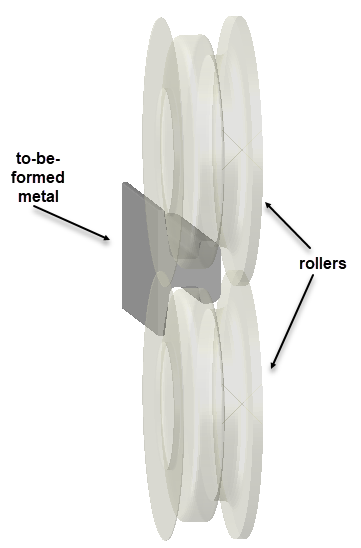
Figure 2: Included geometry
For reasons of symmetry, only one roller and only half of the metal stock is included. The separate parts including mesh are shown in Figure 3. The roller is simulated as an analytical rigid body, and therefore does not require a mesh.
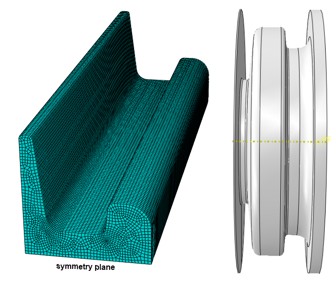
Figure 3: Metal stock part (left) and rigid roller (right)
Material Properties
No material properties are needed for the rigid roller. Since the permanent deformation of the metal during this process is very important, the metal is modelled using elastic-plastic properties. In the current set-up temperature-dependence is not included. Young's modulus and yield stress are lower than at room temperature however, to take into account the influence of the elevated temperature.
Model Set-up
Symmetry conditions are applied. A rotational velocity is prescribed to the roller. An Abaqus/Explicit step is used, with a time period of 0.6 s. A velocity of 10 m/s is prescribed to the metal stock to move it forward. This velocity and step time were chosen so the kinetic energy was small compared to the internal energy in the model, and the analysis is effectively quasi-static. Contact is taken into account with a friction coefficient of 0.3. An overview of this set-up is shown in Figure 4.
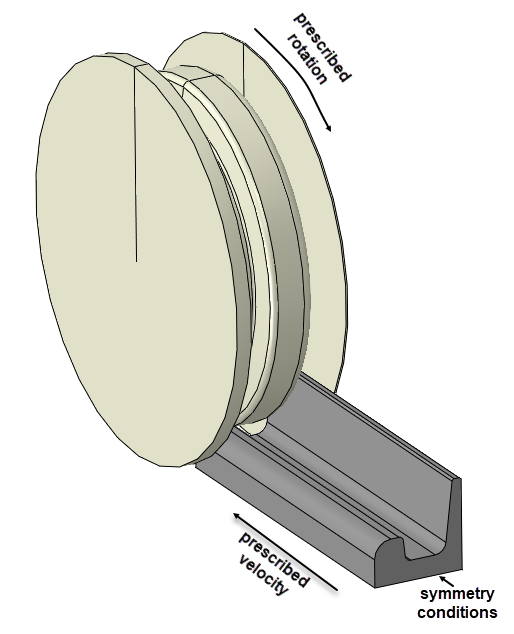
Figure 4: Boundary conditions applied to the model.
Results
During the analysis, the metal is rolled into it's new shape (Figure 5, movies).
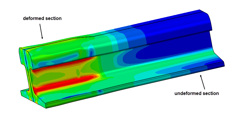
Figure 5: Rail track during forming process.
At the end of the analysis, the shape is clearly modified compared to the starting shape (Figure 6).
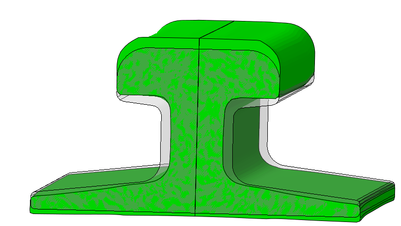
Figure 6: Deformed shape (green) compared to initial shape (gray).
Stresses concentrate at the corners, as expected (Figure 7).
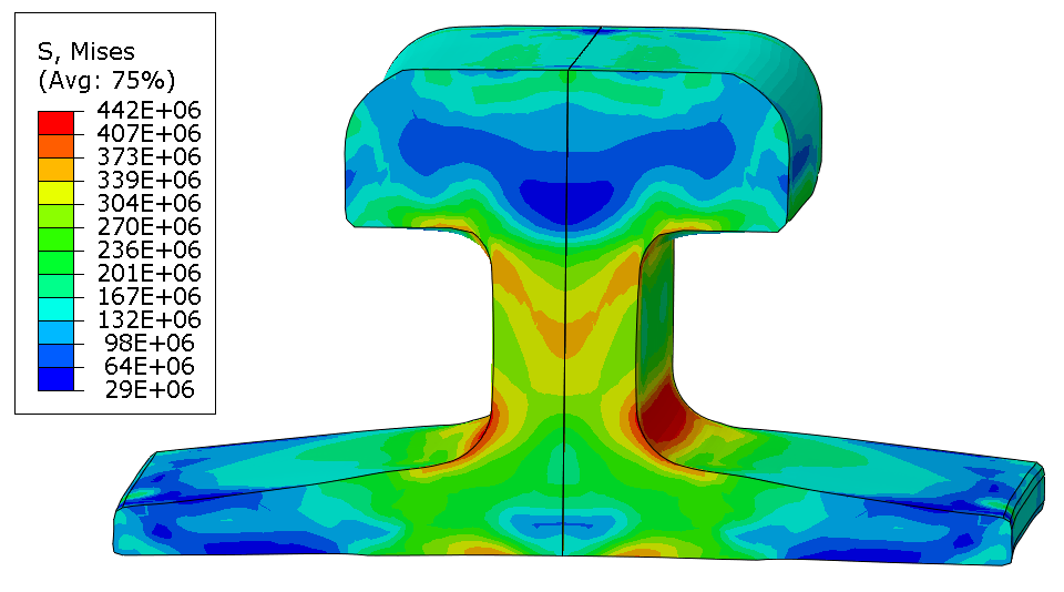
Figure 7: Mises stress (Pa) at the end of the analysis.
Discussion
The current model does not include thermal effects. It is possible to perform a fully coupled thermal-mechanical analysis, including heat exchange between roller and metal as well as convection and radiation with respect to the environment and how this influences material properties and thermal expansion during the process. This makes matters a lot more complex and requires additional material data.
Some elements distort quite a lot during this analysis (Figure 8), as is common for forming analyses of solid (rather than plate) materials. ALE adaptive meshing may help to keep a reasonable mesh during this type of analysis.
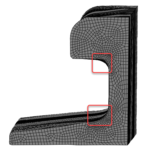
Figure 8: Deformed shape, highlighting distorted elements
If the steady-state situation is of interest then ALE adaptive meshing can be used to feed the material through the mesh. In this case, it is not necessary to simulate the whole part: material moves through a section of it using inflow and outflow conditions.
Currently, one step of the forming process is simulated. To simulate the entire process, a number of analyses is required. This may require further remeshing.
Conclusion
Abaqus offers the tools to include the complexity and large deformations needed to simulate the hot forming process.


TECHNIA Simulation provides top tier FEA, Non-linear, and Advanced Simulation Software, Training, and Consultancy. Our dedicated team of more than 65 Simulation experts across 16 countries advise and support your innovation with a wealth of specialist knowledge and experience.
About TECHNIA- Related news and articles straight to your inbox
- Hints, tips & how-tos
- Thought leadership articles

Helping you find the information you’re looking for. Discover webinars, events, FAQ's, case studies and tutorials.
VIEW HUB