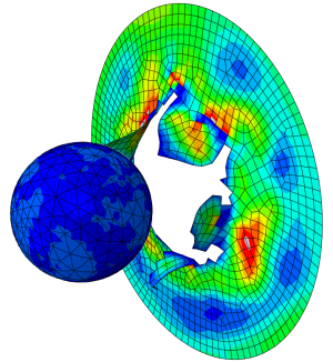
Finite element analysis of stents is challenging. It typically involves small structures, large deformations, complex contact conditions and intricate material definitions. What can Abaqus offer for this type of analysis? In this blog we will find out.
What Are Stents?
Stents are used in medicine to allow flow through a vessel or duct. We will focus here on coronary stents. These are used when a blood vessel that supplies blood to the heart is occluded. The stent, a thin metal structure, is first crimped so it is small enough to pass through the blood vessels on way to the occluded region. Once it is there, the stent is expanded so the vessel opens (figure 1), allowing blood to flow more easily and oxygen and nutrients to be delivered to the heart.
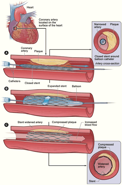
Figure 1: Delivery of a stent in a coronary artery. The plaque reduces the opened area of the artery and the blood flow. The crimped stent is delivered using a catheter and blown up using a balloon. This compresses the plaque and opens the artery so blood can flow. The stent deforms permanently and keeps the artery open. Image from wikipedia.
We will simulate the process of first crimping and then expanding the stent here.
How Can We Get the Geometry?
Stents are often drawn flat, though their final geometry is tubular. Using Abaqus’ wrap mesh plug-in (Figure 2). Flat geometry can be wrapped into a tube.
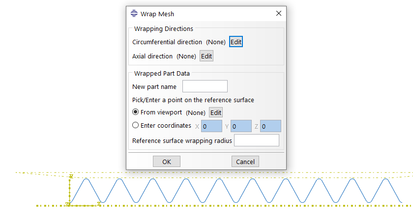
Figure 2: Wrap Mesh plugin.
The plugin requires a mesh(ed geometry) in the assembly module. You provide the circumferential direction, axial direction, name of the new part, origin and the wrapping radius. The plugin will create an orphan mesh of the wrapped tubular structure. This works for shells, solids and beams. In this example, beam elements are used and the result after wrapping is shown in Figure 3.
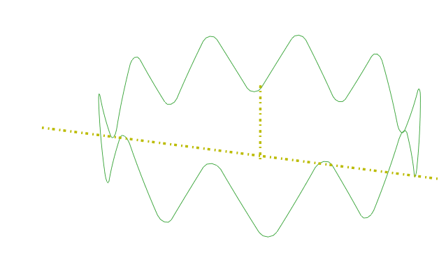
Figure 3: Wrapped mesh
Stents often consist of repeated segments. Multiple instances of this segment are created, to form the complete tube (Figure 4).
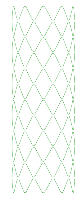
Figure 4: Complete stent. It is approximately 10 mm long and has a diameter of 3.5 mm.
A circular profile with a radius of 0.045 mm is assigned to the structure.
What Materials Are Used?
In this example, a balloon-expandable stainless-steel stent is simulated, comparable to Figure 1. Elastic-plastic stainless steel material properties are defined. Including plasticity is of especial importance, to allow the crimping and expansion of the stent.
As a side note: Abaqus also offers a built-in super elastic material model, that is typically used for self-expanding nitinol stents.
The stent will expand against a blood vessel. Like many human tissues a blood vessel is a composite. It is often modelled as a hyperelastic matrix with families of fibres embedded into it. The Holzapfel-Gasser-Ogden model implemented in Abaqus is intended for this purpose and is used for this example. The families of fibres have a main direction and a degree of alignment with respect to this direction. It is possible to have completely aligned fibres, randomly oriented fibres or something in between where there is a preference, but not all fibres are oriented in this direction. The vessel consists of three layers that have different properties and different main fibre orientations. These were taken from literature. The main fibre orientations are visualised in Figure 5.

Figure 5: Main fibre orientations in the vessel. Each of the three layers has two main orientations, under the same angle from the circumferential direction, but with a different sign. The fibre orientations in different layers are indicated with different colours.
What Loading Conditions Are Applied?
First the stent is crimped (to fit a catheter) and then it is expanded until it is pressed against the vessel wall. The analysis therefore includes the stent, a crimping tool, an expansion tool and the vessel (Figure 6).
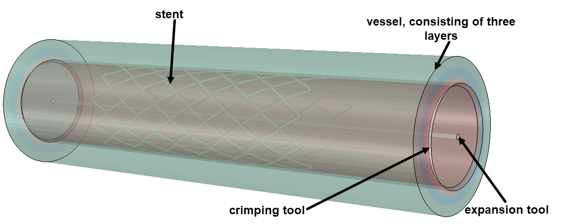
Figure 6: Model set-up for crimp-expansion analysis.
The stent consists of multiple instances of the beam structure shown before. These are locally connected via ties (Figure 7). Because of these local connections, cyclic symmetry conditions cannot be used.
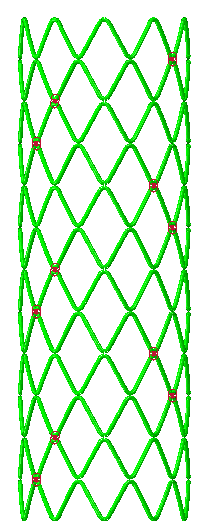
Figure 7: Stent with strut thickness visualized and locations of ties indicated.
The vessel is modelled as a solid. Both tools are modelled using surface elements. The crimping tool initially has a larger diameter than the stent, the expansion tool has a smaller diameter than the stent after crimping.
Four steps are simulated:
- Crimping
- Removal of crimping tool
- Expansion
- Removal of expansion tool
The displacement of the crimping tool is prescribed during the first two steps, the displacement of the expansion tool is prescribed during the last two steps. No other boundary conditions are applied.
How About Contact?
Contact is an important aspect of this analysis: the crimping and expansion tools are in contact with the stent, the stent is in contact with the vessel and different parts of the stent are in contact with each other. On the other hand, the tools should not contact each other and the stent initially overlaps the vessel which should not be an issue. Additionally, the stent struts are modelled as beams, that do not have a thickness on the geometry. The beam radius should be accounted for in the contact.
All these effects can easily be included using Abaqus’ general contact. The radius of the struts is accounted for automatically. By default general contact includes contact between all surfaces. At the start of the analysis, the vessel and expansion tool are excluded from the contact. At the start of step 3, the vessel and expansion tool are included, and the crimping tool is excluded. Friction is considered.
The analysis is performed using Abaqus/Explicit. The small time increments and absence of the need for convergence, make it easier to find a solution to a complex contact problem such as this.
What Are the Results?
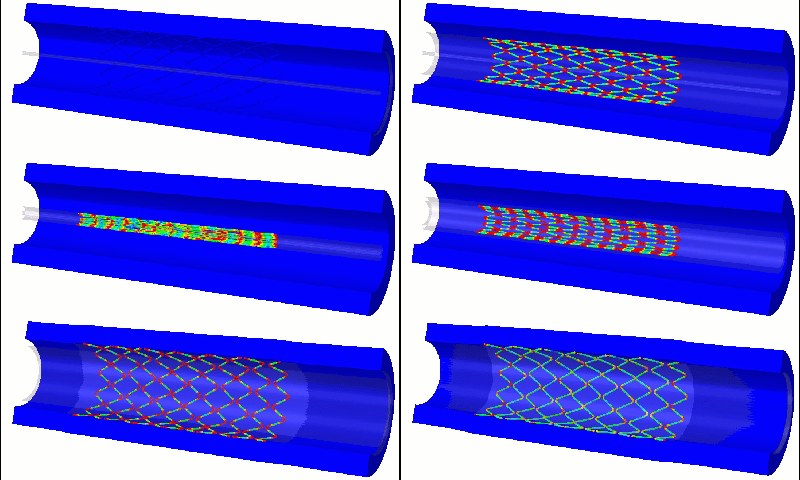
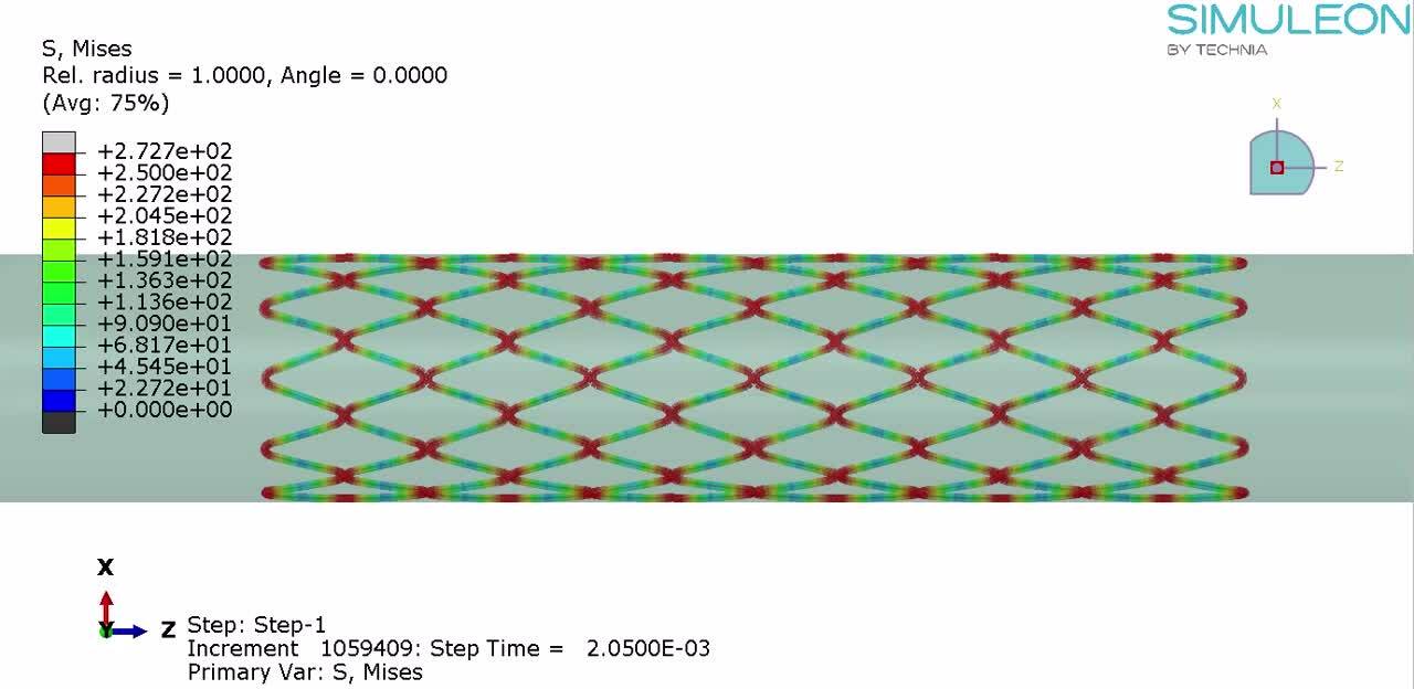
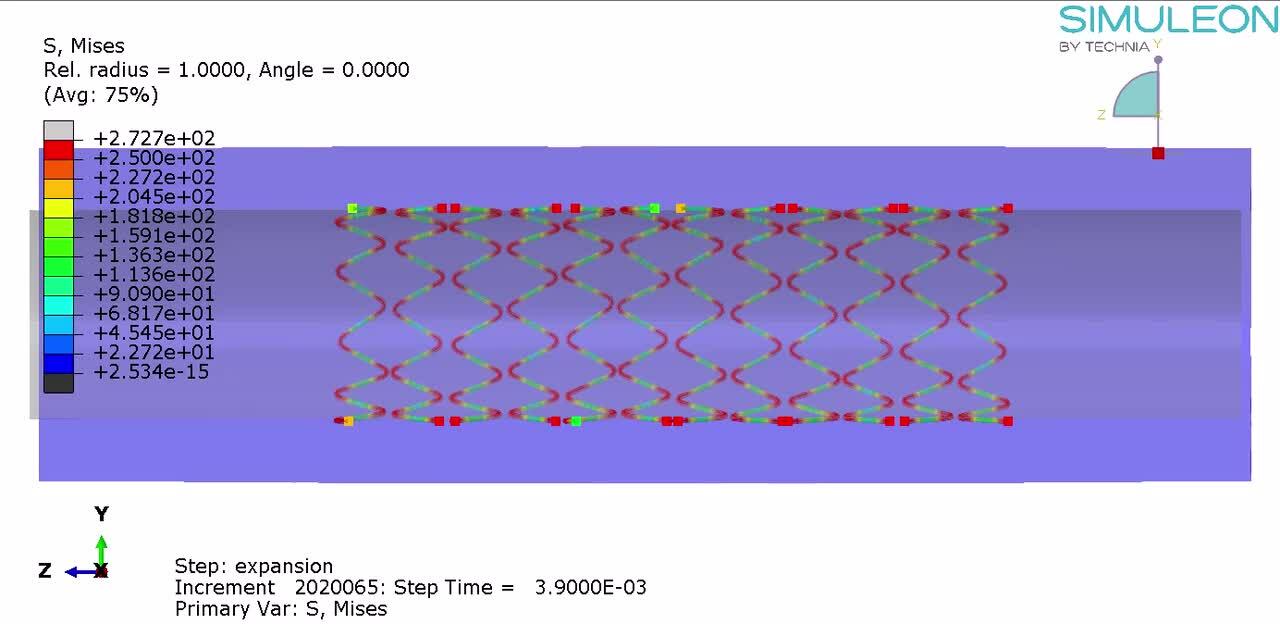
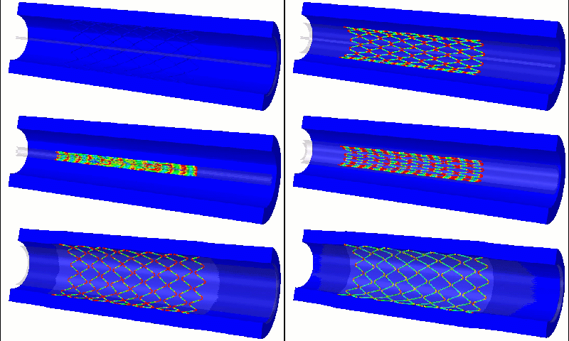
The stent is crimped to a small diameter. The contact conditions ensure there is no overlap between different regions. Stresses are localized to the rounded parts of the struts, exceeding the tensile limit in this region. Since this is a design that I drew myself to resemble a stent, there is a lot of room for improvement on the geometry.
After the crimping phase, the crimping tool is removed, leading to elastic spring back. The final diameter of the crimped stent, is slightly larger than the minimal inner diameter of the crimping device. The analysis shows how big the difference is.
Then the stent is expanded in the vessel. The vessel moves outwards, especially where the stent is located. When the expansion tool is retreated, the vessel partially moves back, but is opened a bit more than it initially was. In this example I did not include a plaque, the effect would be more clear If that would have been the case.
These analysis show the final shape of the stent, including the new internal diameter of the vessel, once it is opened. It also shows the stress levels in the stent. These can be used to assess whether this stent design can withstand the intended loading.
On Boundary Conditions and Symmetry
One of the interesting choices for this type of analysis is the choice of boundary conditions - whether the movement op points on the geometry is restricted and if so where and how. In this case, boundary conditions where only applied to the tools, not to the stent or the vessel. The stent then has a lot of freedom to deform. This can be good, because you are not unnecessarily restricting it, but also bad because there could be non-physical movements, especially if the loading is rather quick to increase the run time. Ideally, we want to avoid motions of the entire structure, while allowing more local motions. This cannot be directly prescribed.
Sometime symmetry conditions can be used: if there is symmetry in the model, then both halves should behave the same way. Only part of the structure needs to be simulated which reduces the size of the model and the simulation time. The geometry cannot move off the symmetry plane, limiting the motion of the stent in a realistic way. The lack of symmetry in the current model, due to local connections between the stent rings, did not allow this approach.
What Else Can We Do?
The current example was quite simple and intended to show the principle. In practice, different people have a different vessel geometry, possibly including bends and bifurcations. Plaques can occur at different locations, and they can have different sizes. Simulations of patient specific geometry can help assess which stent is most suitable for which patient.
Positioning the stent is only the start. When the stent is in service, it is cyclically loaded due to the pulsatile blood flow. Given a normal heart rate of 60-80 beats per minute and a stent lifetime of 10 years, the stent should survive hundreds of millions of cycles. Fatigue behaviour during this period is important and it can take very long to measure experimentally. Simulations can be used for this.
For this kind of medical applications simulations are especially useful due to ethical limitations in the experiments that can be performed. While for many products it is possible to try out many options to determine what is best, we do not want to do that with people.
Conclusion
Abaqus has a lot of potential for stent analysis. General contact takes care of even complex contact conditions such as contact between the outer surface of beam elements in a user-friendly way. The choice between an explicit and an implicit solver in a single package makes it possible to try out both and/or do part of the analysis with one solver and another part of the analysis with the other. The inclusion of superelastic and Holzapfel-Gasser-Ogden material models in the Abaqus material library allows most materials that are relevant for stents to be simulated with built-in materials.
Though stent analysis is challenging, Abaqus offers the tools to make it possible.

