

Posted by Endre Stedje
Table of contents
The Norwegian Formula Team
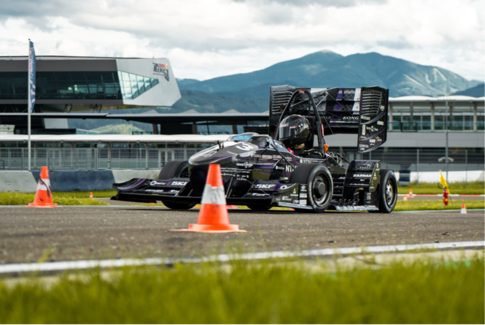
Formula Student is the largest engineering competition for students in the world. Revolve NTNU is a Norwegian Formula Student racing team consisting of 68 dedicated students.
During the 2023 season, we achieved 4th place overall in the most competitive event in the world, Formula Student Germany. My position in the team consisted of weight/stiffness optimizing the uprights and hubs in our wheel-assembly. My experience with design prior to this consisted mainly of CAD, which meant that Abaqus had to be usable for me within a few months. This was the beginning of an exciting and demanding development process.
What is an Upright?
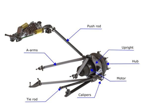
An upright is the structural component that holds the suspension together inside the wheel. On our car, it supports the motors, brake calipers, suspension rods, steering system, and planetary gearbox within the hub.
But the upright is more than just a bracket holding components together. It is a crucial part that transfers loads from the wheel through the outboard suspension rods and further inboards.
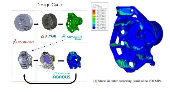
As for the loadcases, there are six different ones it has been topology optimized for. The two toughest cases are 2g bump + outer corner turn at 112 km/h and 2g bump + brake at 112 km/h.
While dimensioning a part with such high performance demands, cutting all unnecessary weight must be done as well, since the whole car only weighs 163 kg. The front uprights weigh 930 grams and the rears are 800 grams, both 5-axis machined from a 7075-T6 bolt.
Topology Optimization
As the upright is such a complex part with regard to the loadpath of different loadcases and interacting components, a topology optimization with Tosca Structure was made.
In the topology optimization, six different load cases were used. These were calculated with data from our self-developed telemetry program, Revolve Analyze. The optimization was about 95 % accurate to map out where material should be prioritized. It was reductive and started off with a design space within the rims with as much material as possible.
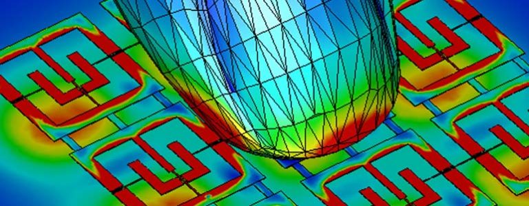
A topology optimization gives a nature-like structure design to ensure the least strain through the component during operation. This optimization has a priority to be stiffer about the camber and toe rotations as these are crucial rotations for the function of the component.
The rear uprights on the car are different, so a separate topology optimization had to be made for each of them. This had to be done since the rear brake calipers aren’t symmetrical about the mirror plane. The front ones could be mirrored. Since computing power was a bottleneck during the topology optimization, the model had to be way simpler than the Abaqus version, and it still needed 26 hours to complete.
Finite Element Method
Topology optimization results were used to construct a mechanical viable part in SOLIDWORKS and Abaqus. Validation of the component was done through Abaqus and the last iterations of the geometry arose from it.
This model has the same goal as every other: make it as realistic as possible. But, due to such a short development time (three months), reduced processing power and prioritization of data, there had to be some simplifications.
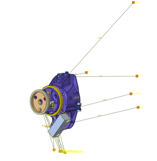
The model is based on suspension rods as link connectors that are locked in displacement where they end at the monocoque. This reduces complexity as neither carbon rods nor their respective brackets had to be used. It removed five carbon rods and seven brackets.
As with regular cars, all forces that act on the upright originate from the contact patch of the tire. It is such in the FEM model as well, but the loads travel straight from the contact patch through beams instead of the tire, rim, and hubs.
The beams end at the centerpoint of a coupling to the outer ring of each wheel bearing. Although this is quite conservative since loads realistically travel through more components, this reduces the already high complexity. However, the displacement of the tire at the contact patch during different load cases was included, since this affects where the loads originate from.
Validation
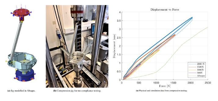
Both physical and simulation based validation was done through the year to see if the FEM model was realistic. The simulation-based one was a vast simplification of the setup to see if it was comparable to the complex one. In the physical test, a spare upright was used in a compression jig to check for compliance correlation between Abaqus and physical.
As the graph shows, the Abaqus model has too little displacement, initially, but it correlates nicely from 1000 N and up. The theory - as to why this occurs in the beginning - is that Abaqus gets rid of the initial conditions, such as contact.
Another important validation of the FEM model is the decade or more of experience that the team has with developing uprights. The FEM model has been improved each year and has a strong foundation. Uprights have been battle tested and proven to work as intended, even with some faults that occurred during fabrication. With such a long history of success, we trusted that the whole development process would be functional.
 Gratitude of Supporters
It was such a fantastic year at Revolve NTNU. The level of competitiveness and innovation-driven design is world-class and simply cannot be found in any other student organization in
Norway.
With no prior experience in FEM simulation, a position like this was truly an
adventure. It was absolutely necessary to have alumni and courses by TECHNIA with me in
clueless situations. Huge thanks to the Alumni and sponsors who helped us make this
possible.


TECHNIA Simulation provides top tier FEA, Non-linear, and Advanced Simulation Software, Training, and Consultancy. Our dedicated team of more than 65 Simulation experts across 16 countries advise and support your innovation with a wealth of specialist knowledge and experience.
About TECHNIA- Related news and articles straight to your inbox
- Hints, tips & how-tos
- Thought leadership articles

Helping you find the information you’re looking for. Discover webinars, events, FAQ's, case studies and tutorials.
VIEW HUB