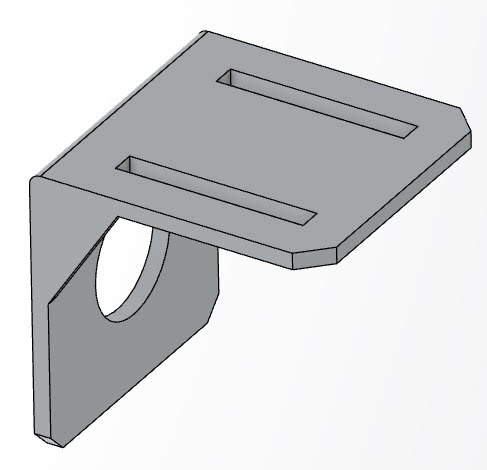
As a consultancy company, we regularly receive geometry files from external parties. Typically this geometry isn’t ideal for simulation purposes: it includes details that are not of importance for the analysis, while they will negatively impact meshing and simulation time. Therefore, it is beneficial to remove some of the features from the geometry (defeature it) for simulation purposes.
Often the best way to do this, is by supressing features that are not needed in the original design. However, this is often not possible when the geometry is obtained from an external party, that may use different design software. Also, it may not be clear what can be safely removed or suppressed, without messing with the rest of the model.
Because of this, we often end up trying to remove features - such as text, fillets or holes – from e.g. step geometry. To a certain extent this can be done in Abaqus. It typically involves removing part of the geometry, creating new faces to cover any openings created and recreating a solid from the shell outline that has been obtained this way.
In this blog, I’ll show some of the defeaturing options of the Simulation Model Preparation App on the 3DEXPERIENCE Platform. As an example geometry, I’ll use the bracket shown in Figure 1, that has some text, fillets and holes are not be needed for the simulation analysis.
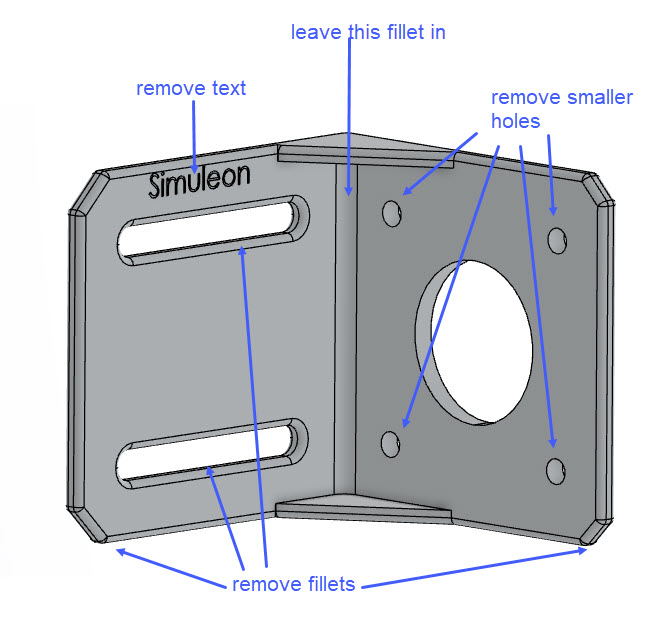
Figure 1: Geometry as imported, including the features to be removed.
I’d like to emphasize that I imported this geometry from a step file. This means that the file is external to the 3DEXPERIENCE Platform (no feature tree is available) and the tools that I will show here work on geometry in general, not only that developed in the platform.
Defeaturing
In the Simulation Model Preparation app, the ‘defeature’ tab contains the ‘Defeaturing’ command. This is capable of removing most of the features we want to get rid of in just a few clicks. From the Defeaturing dialog box, filters can be created, to remove logo’s, chamfers, fillets and holes (Figure 2).
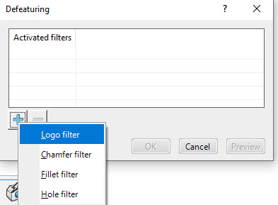
Figure 2: Defeaturing dialog box, indicating the types of filters that can be made.
For each filter, minimum and maximum sizes can be defined. In this case, I’ll use a Logo filter without minimum or maximum, since there is only one logo and that has to be removed. When the filter is created, then clicking on the ‘preview’ button shows what will be removed in purple, making it easy to determine whether the behaviour is as intended.
I also want to remove the smaller holes, while leaving the larger holes intact. I happen to know that 10 mm is a suitable cut-off, so this is filled in as maximum diameter (Figure 3).
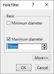
Figure 3: Specifying a maximum diameter for holes to be defeatured.
Finally, I want to remove the fillets. For the fillets, a minimum and maximum radius can be specified. In this case, that is not of any use, since all fillets have the same radius. Still, I want to keep the fillet in the middle (front and back) while getting rid of all other fillets. To my knowledge, it is not possible to manually specify features to keep during filtered defeaturing, so I need to find a way to have (most of) the fillets removed that I don’t want, without remove the ones that I want to keep.
Figure 4 shows the available filter options.
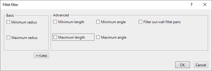
Figure 4: Filter options for fillet filter.
Looking at the geometry, then the fillets I want to keep are longer than most of the others. If I make a filter with a maximum length I will probably get rid of most of the unwanted fillets, and afterwards I can use a different tool to remove any remaining fillets if needed.
The question is then: what cut-off value should I use? Or: how long is the edge I want to keep? To answer this question, I select the physical product at the top of the model tree and go to the 3D markup tool. There I can easily measure the length of the fillet of interest (Figure 5).
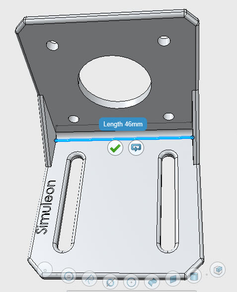
Figure 5: Measuring the length of the fillet of interest using the 3D Markup app.
Based on this information, I decide to make the Maximum length slightly smaller at 45 mm. (By the way: the 3D experience platform uses units, so I could also fill in a value in e.g. inches and it would automatically convert things! 😊)
The ‘preview’ button then shows this (Figure 6):
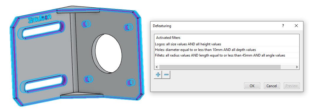
Figure 6: Preview of the result of defeaturing.
The final geometry is shown in Figure 7, this is what I had in mind.
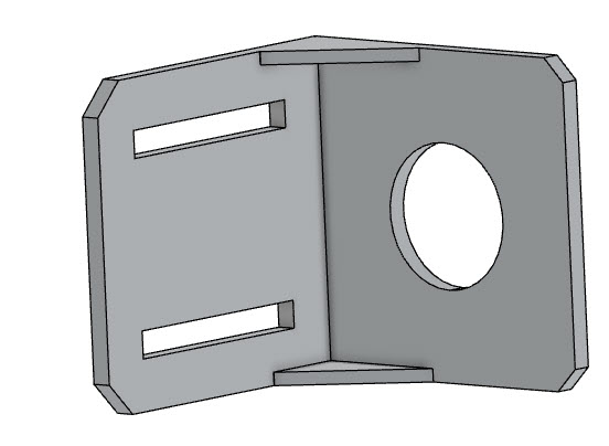
Figure 7: Geometry after applying defeaturing filters.
Rotating it shows that there are some fillets left on the back. These can be removed using the ‘remove face’ tool. Selecting the filleted edges as faces to remove, gives the intended effect.
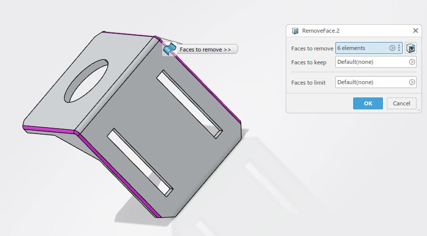
Figure 8: Removing the remaining fillets using the remove faces tool.
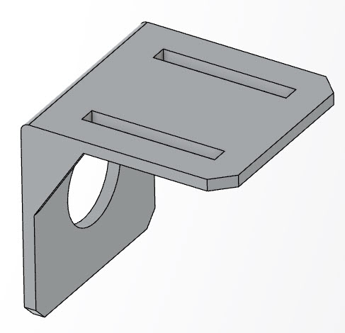
Figure 9: Fully defeatured geometry.
This is a solid part that can be meshed and everything, created in less time than it takes you to read this blog. The filters are features in the model tree, that can be modified later on if necessary.
The process of defeaturing is shown in the movie below.
This is summarized in Figure 10.
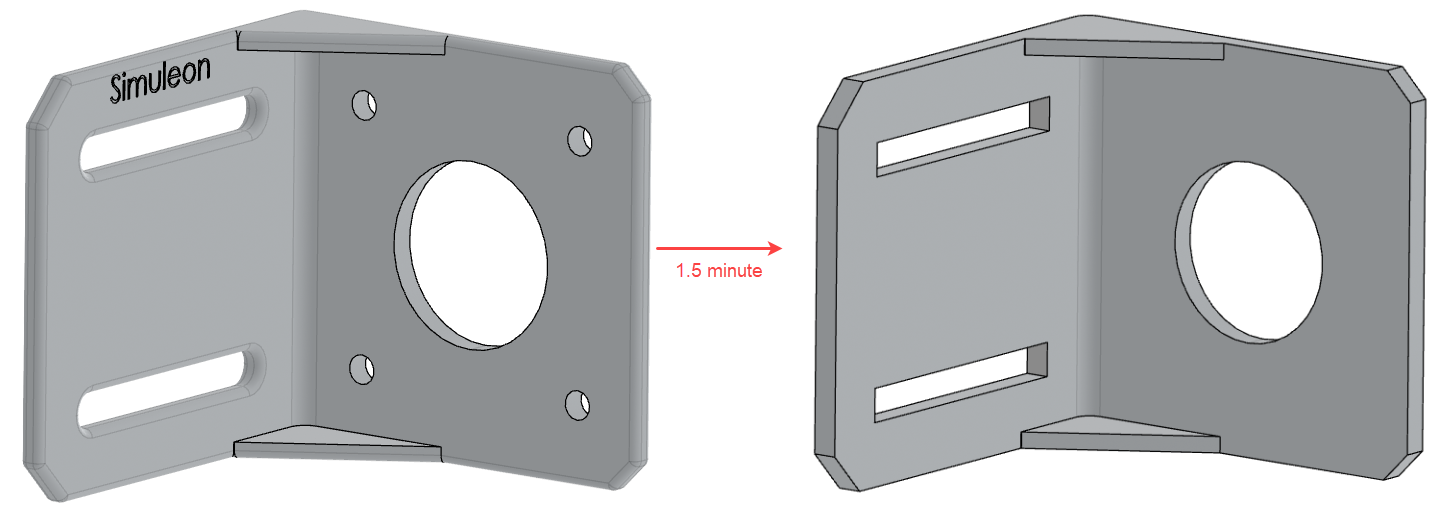
Figure 10: The initial and final geometry.
All in all, I think this is a very nice capability of the 3DEXPERIENCE Platform!

