
Posted by Dolf Broekaart
Table of contents
It happens all the time. Too often we still see companies that trust on simulations being performed with a solid-mesh, while the geometry is thin walled, like with sheet-metal, extruded parts or plastic parts. If you ask the people why they didn’t use a shell mesh, most of the time they will tell you it will take too much time to generate a mid-surface shell model, or they think it is not feasible capturing the necessary detail in the analysis, so they decided to just ignore the rules.

Below we have listed why creating a mid-surface shell model is still favourable.
- Accuracy of the end result can be way off with solid mesh elements
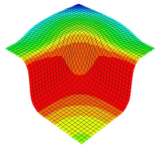
Whether you have followed a basic course from a CAD-integrated FEA software, or from a stand-alone High-End FEA software, they will all teach you to create shell meshes for thin-walled parts. Even if you setup a simple thin-walled beam and let it suffer under bending, you already see differences in both stress and displacement for a solid mesh versus a mid-surface shell mesh. Particularly when the solid mesh approach is a course mesh, the effects are even bigger. When you refine the solid mesh, the results will become more accurate, but you will need quite some iterations to have mesh convergence. - The solid mesh approach, which needs 3 to 4 elements across the thickness, results in huge amount of elements and long running times
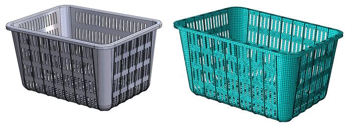
If you do decide to take the solid mesh approach, please be aware that you need a minimum of 3 to 4 elements across the thickness to capture all bending and stiffness effects to generate an accurate solution. For products that don’t look like a simple beam, it can potentially create huge number of elements, resulting in large running times. If you think of injection moulded parts with ribs, draft angles and fillets and other types of typical geometry, the necessary amount of elements will be enormously and therefor the running times will be huge. We have seen differences for injection moulded parts with a shell approach that take 1 hour to run, while with a proper solid mesh including 3 to 4 elements across the thickness the running time could potentially be somewhere between 5 to 10 days per simulation run. - Meshing nasty geometry with solid mesh elements needs preparation too
For a lot of the standard meshing techniques, the solid mesh needs to be as small as the smallest detailed geometry in the model. We receive a lot of files from customers that contain sliver faces, short edges, surfaces that do not align, etc. Simply pushing the mesh button won’t do the trick here since the system will most likely tell you it is unable to mesh. So you need to clean-up the geometry anyway, which also for a solid part can be quite a hassle. Sometimes switching to a curvature based mesher can do a part of the trick, but you can potentially lose the necessary detail. Since you need to clean up this geometry anyway, why not define a mid-surface model from the original model? - Post processing of huge amount of solid element simulations takes ages
It seems to be trivial, but often overlooked. The time that you will need for running these huge amount of element simulations, also contributes to the potentially frustrating post processing of the end results. Ever needed to wait for more than 30 minute to generate one simple stress plot, or even a few hours to generate a single animation? Or what about non-linear simulations with more than 100 time steps and the results of those? Once you have been in that situation of generating huge amount of data, you will hopefully try to prevent that in other projects. - The shell mesh approach creates a fast running accurate simulations
Since the amount of elements is less for the shell approach, because the wall thickness is captured as a mathematical value instead of actually modelling the thickness, there will be less equations to solve. This results in simulations that run in minutes or an hour instead of days to weeks. That also means that a shell mesh approach can be easily used to perform iterative simulations. Another benefit is that changing the wall thickness in your simulations with the shell approach are easy, and you will see the results of those changes in a very short time.
 Other Considerations When Creating Mid-surface Shell Models
Of course the creation of a proper mid-surface mesh model is not an easy task. It comes with the hurdles of surface trimming, surface knitting, surface splitting, surface deleting and patching, etc. You also need to think of where you would like to setup the model. In the native CAD program, or in your standalone or cad-integrated simulation software?
Are There Any Shortcuts When Creating a Mid-surface Shell Model?
It would be great if we could tell you there is an automatic kind of software doing all this labour intensive work for you with a push of the button, but unfortunately this is not the case. At the end it still comes down to lots of clicking and manual labour.
What could be considered is to share some thoughts with the designers upfront. If they would setup their 3D model from scratch as a surface model and later thickening those surfaces to apply the proper wall thickness, the mid-surface model could be generated in minutes instead of days. But of course this would influence the modelling behaviour of the designer, and if this is not really valuable to them, they most likely won’t do this. Persons who are acting both as a designer and a simulation engineer will clearly see the benefits of this typical approach.
How to Force a Compatible Mesh for Shell Elements?
When you create a mid-surface shell model, the surfaces that are intersecting won’t have overlaying nodes automatically. This will cause parts or ribs that don’t have proper contact conditions and just don’t contribute to the stiffness of the structure, but just intersect with the whole model not building up any reaction forces or stresses. This can be solved by splitting or partitioning the surfaces on such a way that the intersecting surfaces are splitted or partitioned on the edge that they share in common. On this way you will force an automatic compatible mesh where the nodes are perfectly aligned with each other.
Can All Details Be Captured?
For some detailed geometry it can be quite hard to create a mid-surface model from. In other cases it is not feasible at all. Even in those situations, you could consider a submodelling approach. So inevitably solid meshing the necessary detail, but using shell surfaces for the surrounding geometry can still do the trick. Of course you do need to pay attention to coupling those solid and shell geometries together again.
Creating Mid-surface Shell Geometry in 3DCAD?
Modern type 3DCAD software will come with comprehensive and powerful surfacing capabilities, which tend to be more powerful than the capabilities available in stand-alone simulation software. For most of our mid-surface shell model generation we use SolidWorks in our company. Of course SIMULIA Abaqus also has capabilities of creating such, but as you could expect, a proper 3DCAD program just offers better capabilities to reach your goal faster. So depending on the complexibility and the amount of trimming work we decide to use Abaqus or SolidWorks.
Once the model is finished in SolidWorks, it can be easy read into Abaqus to start the simulations with.
Can a Shell Model Contain Variable Wall Thicknesses?
Dedicated standalone FEA software like SIMULIA Abaqus can apply variable wallthicknesses on a shell mesh. There are many different specifications that can be used for applying the necessary thickness differences to you model.
Do you find it difficult to work with shell meshes and setting up these geometries?


TECHNIA Simulation provides top tier FEA, Non-linear, and Advanced Simulation Software, Training, and Consultancy. Our dedicated team of more than 65 Simulation experts across 16 countries advise and support your innovation with a wealth of specialist knowledge and experience.
About TECHNIA- Related news and articles straight to your inbox
- Hints, tips & how-tos
- Thought leadership articles

Helping you find the information you’re looking for. Discover webinars, events, FAQ's, case studies and tutorials.
VIEW HUB