
Posted by Tomasz Jankowiak
Table of contents
Summary
This Technology Brief presents the results of a numerical simulation of the perforation of a thin steel plate by a rigid projectile in Abaqus/Explicit [1]. The thickness of a square plate with a span of 100 mm is 1 mm. In contrast, the mass of a projectile with a diameter of 13 mm is 30 g. The residual velocity of the projectile is determined for an initial velocity of less than 180 m/s. The influence of the projectile shape on the residual velocity and the failure pattern of the perforated plate is determined.
These results are compared with experimental tests in which both the VR - V0 curve and the failure pattern are determined directly. The most important element of the simulation is the use of a constitutive model, ensuring that the constitutive model is sufficiently sensitive to the strain rate [2] and that an appropriate failure criterion is used taking into account the influence of the triaxiality factor [3].
Background
The process of a steel plate being impacted and penetrated by a projectile has been analysed both experimentally and numerically [4,5] for a long time, but it remains a complex and interesting problem. The most important elements affecting the ballistic properties of the plate are its thickness and strength. During the impact and eventual perforation of the plate, high strain rates occur in the material (of the order of 100000 1/s) and there is a significant increase in temperature (by up to 500 ℃), which affects the mechanical properties of the analysed material. The size, shape, mass and hardness of the projectile as well as the impact velocity and angle of incidence are also important aspects affecting the dynamic behaviour of the plate. This Technology Brief concentrates on the ballistic capacity of plates, with the varying factor is the projectile’s nose shape, Fig. 1.
The process of impact and penetration of a steel plate by a projectile has been studied both experimentally and numerically for a long time [4,5], but it remains a complex and interesting problem. The most important elements affecting the ballistic properties of the plate are its thickness and strength. During the impact and possible perforation of the plate, high strain rates occur in the material (of the order of 100000 1/s) and there is a significant increase in temperature (up to 500℃), which affects the mechanical properties of the material analysed. The size, shape, mass and hardness of the projectile as well as the impact velocity and angle of incidence are also important aspects affecting the dynamic behaviour of the plate. This Technology Brief focuses on the ballistic performance of steel plates, where the varying factor is the nose shape of the projectile, Fig. 2.
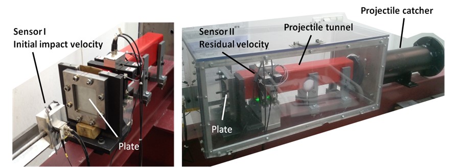
Fig. 1. Experimental setup used for impact tests [5]
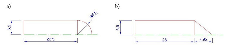
Fig. 2. Projectile shapes used during perforation tests: A) Hemispherical projectile; B) Conical projectile
Ballistic perforation tests have been carried out on 1mm thick IF steel plates impacted by rigid projectiles with different nose shapes. The experimental apparatus used for the realization of ballistic impact tests consist mainly of a gas launcher, Fig. 1, and laser sensor required for the recording and the processing of data provided by the tests: measure the initial and residual projectile velocities. The initial velocity of the projectile is measure just behind the launcher tube and the residual velocity is measured behind the plate. The two kinds of projectile are used in this study: with conical and hemispherical nose shapes, Fig. 2. The projectiles are machined from maraging steel. After the heat treatment their yield stress reaches 2 GPa. For each configuration the projectile mass and diameter are kept constant (MP ≈ 30 g and ϕp = 13 mm).
During the test the projectile impacts the target (square plate with active part 100 * 100 mm2) in the central zone, Fig. 3. The active part has the 1mm thickness and is embedded on a rigid support (clamping part). In order to fully determine the ballistic curve of the steel plate, a wide range of initial impact velocities are considered.
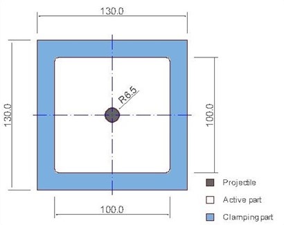
Fig. 3. Geometry of the IF steel plates for perforation (thickness 1 mm)
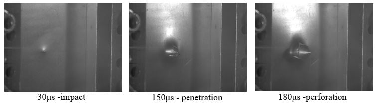
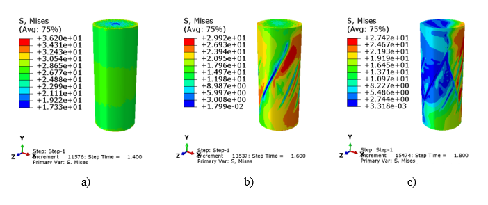
The impact tests are recorded using high speed camera (Phantom v711). The perforation process is recorded with time resolution of 30 μs. In case of the conical projectile three sample configurations: impact, penetration and perforation for initial projectile velocity of V0 = 178 m/s are presented in Fig. 4.
Numerical modeling
Subsequently, numerical analysis of projectile impact and perforation tests on thin steel plates is carried out to predict experimental observations. ABAQUS/Explicit finite element code is used to simulate the process.
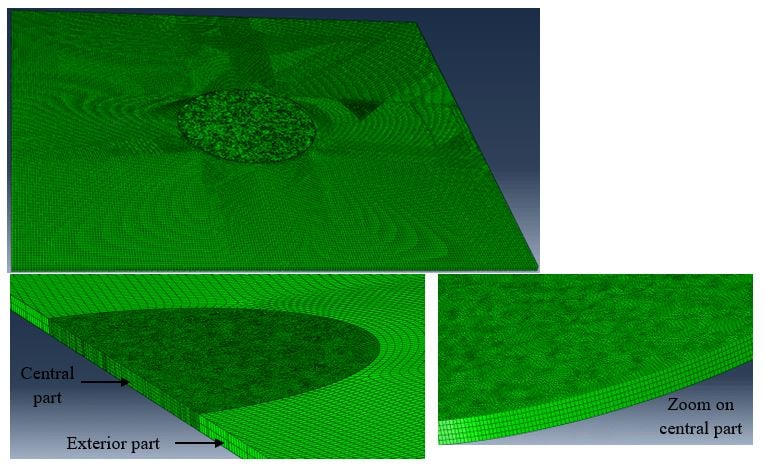
Fig. 5. Discretization of the target
The following main assumptions are introduced in computer analyses:
a) The projectiles are modelled as a three-dimensional non-deformable rigid body constrained to a reference point. Then the mass and moments of inertia are automatically calculated based on the shape, volume and density of the projectile and assigned to its reference point. Numerical simulations are performed for a wide range of initial impact velocities (20 m/s ≤ V0 ≤ 200 m/s) to cover the range of experiments.
b) The contact between the projectile and the plate is modelled using eroded (interior surface) general contact using the penalty method (finite sliding formulation). The constant coefficient of friction μ = 0.2 is applied [4,5].
c) In order to optimize the mesh, the geometry of the plate is divided into two parts: a circular central part (diameter 30 mm) and an exterior part, see Fig. 5. The central part of the plate is meshed using C3D8R 110k elements (size 0.2 mm), while the external part is meshed using 73k elements C3D8I (size 0.5 mm).
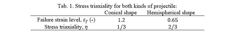
d) The IF target was modelled as RK thermo-visco-plastic material described in [2,4,5]. To reproduce the failure pattern during perforation it was necessary to use failure criterion proposed by Wierzbicki [3]. In this criterion the equivalent strain at failure εf was a function of the stress triaxiality η (the ration of the mean stress σm to equivalent stress ![]() ). A finite element was removed from the mesh when the plastic equivalent strain exceeds the limit value εf. The average value of the stress triaxiality was estimated just before the failure of the target for both projectile shapes, see Tab. 1.
). A finite element was removed from the mesh when the plastic equivalent strain exceeds the limit value εf. The average value of the stress triaxiality was estimated just before the failure of the target for both projectile shapes, see Tab. 1.
Comparison of the experimental and numerical results
The results obtained from the numerical predictions in terms of ballistic curves VR - V0 are compared to experiments for both projectiles and are presented in Fig. 6.
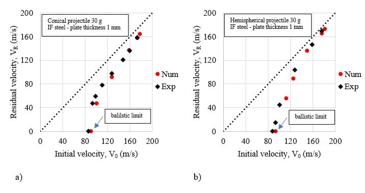
Fig. 6. Definition of the ballistic curves from experiments (Exp) versus simulations (Num)
for: a) conical projectile, b) hemispherical projectile
A small difference is observed for impact velocities close to the ballistic limit, see Fig. 6. However, a good global agreement with the experimental results is visible. Numerical predictions of the ballistic limit velocities are 90m/s for the conical projectile and 93m/s for the hemispherical projectile.

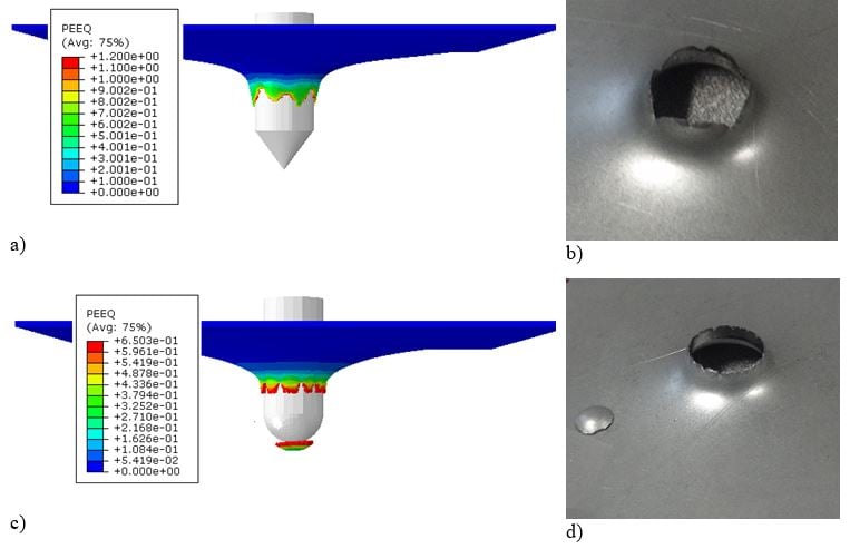
Fig. 7. Comparison between the failure modes obtained numerically: a) conical projectile, c) hemispherical projectile and experimentally: b) conical projectile, d) hemispherical projectile.
The failure modes obtained experimentally are reproduced numerically, see Fig. 7. Numerical results show a failure mode by petals forming for conical projectile nose shape. For the hemispherical projectile, a plug ejection failure mode is observed. The maximum equivalent failure strain corresponds to that set by the failure criterion for each projectiles shape, see Fig. 7 and Tab.1.
Conclusions
Experimental and numerical investigations have been made on an IF steel subjected to impact and perforation loading. The mechanical behaviour of the plate material has been implemented in the code using the RK constitutive relation [2]. Material tests were performed to determine the material constants for the constitutive relation proposed by Rusinek and Klepaczko [2]. Two different shapes of projectile were considered in this Technology Brief (conical and hemispherical). The ballistic limit for each projectile shape was determined and the ballistic curves plotted. It is found that the ballistic limit, the failure mode of the target are strongly linked to the projectile nose shape. A numerical analysis of the impact problem has been made using the finite element code ABAQUS/Explicit. The results obtained from the numerical part were compared to experiments and a good agreement is observe in terms of failure mode, ballistic limit and ballistic curves.
References
[1] Abaqus. Abaqus/Explicit User’s Manuels, Version 2022.
[2] Rusinek A, Klepaczko JR. Shear testing of a sheet steel at wide range of strain rates and a constitutive relation with strain-rate and temperature dependence of the flow stress. Int J Plast 2001;17:87–115.
[3] Wierzbicki T, Bao Y, Lee Y-W, Bai Y. Calibration and evaluation of seven fracture models. Int J Mech Sci 2005;47:719–43.
[4] Jankowiak T, Rusinek a., Wood P. A numerical analysis of the dynamic behavior of sheet steel perforated by a conical projectile under ballistic conditions. Finite Elem Anal Des 2013;65:39–49.
[5] K.M. Kpenyigba, T. Jankowiak, A. Rusinek, R. Pesci, B. Wang, Effect of projectile nose shape on ballistic resistance of interstitial-free steel sheets. Int J Plast 2015;79:83-94

TECHNIA Simulation provides top tier FEA, Non-linear, and Advanced Simulation Software, Training, and Consultancy. Our dedicated team of more than 65 Simulation experts across 16 countries advise and support your innovation with a wealth of specialist knowledge and experience.
About TECHNIA- Related news and articles straight to your inbox
- Hints, tips & how-tos
- Thought leadership articles

Helping you find the information you’re looking for. Discover webinars, events, FAQ's, case studies and tutorials.
VIEW HUB