
Posted by Dolf Broekaart
Table of contents
The Introduction
 The geometry describes a PET bottle which can contain 0.5 l of drinkable liquid. Performing a top load analysis is important to determine the vertical stiffness of the bottle. This top load is also important to determine the vertical stack ability.
The squeeze load can be performed with or without liquid, and with or without closed cap (building up pressure). In this example we have setup a squeeze load without liquid, without a cap. (so no internal pressure)
The crush load goes beyond the top load simulation, and continues the calculation where the top load stops. Normally the top load analysis shows the force versus displacement graph, and at the point the force is decreasing, the analysis stops. For the crushing load we can continue the analysis to see how the bottle is folding or buckling.
How Do We Approach This?
1. Starting With the 3D-geometry
As in most of our simulations, we start with the 3D-CAD model (in this particular case from SOLIDWORKS). The bottle was drawn in solids. For accurate and fast analysis the best approach is to use a shell mesh. So we have taken a mid-surface offset from the solid model and created a single-surface model from that. By using the Associative interface, we have imported the SOLIDWORKS Surface model into Abaqus CAE. After reviewing the quality of the geometry, we saw that some faces were not necessary, and others should be included. By using the Virtual Topology in the Mesh module, we were able to combine faces to get rid of the unnecessary ones.
2. The Meshing Process
When we meshed it the first time, we saw quite some elements with a bad aspect ratio. In order to generate a more symmetric mesh we decided to partition the model. Of course this is possible in Abaqus as well, but since we have the Associative interface running, we simply did this in SOLIDWORKS and updated the model. The model now looks like this.
After remeshing it, we now have a quite reasonable hex-mesh that now looks like this.

3. Applying Material Specifications
To continue our journey, we needed to apply the correct material specifications to the model. In this case we used a stress strain curve for the PET-material that we received from a plastic producer. So we imported the correct  stress-strain data, created a homogeneous shell section with a wall thickness of 0,6 mm and applied the section to the bottle. For the application surfaces for pre-displacement and the bottom we chose steel.
4. Creating an Assembly
We created an assembly, and also drawn a top surface to apply the pre-described displacement. We remeshed all the parts and continued to the next step.
5. Creating an Analysis Step
In the step creation, we determine what kind of analysis we would like to add to the simulation. In this first case we took Static General and switched nlgeometry ON.
6. Determine Interaction
In the interaction module we need to specify contact. Because of buckling behaviour, we can potentially expect some self-contact, so in this case we have chosen to use general contact with a friction coefficient of 0,2.
7. Loads and Boundary Conditions
For the lower surface we applied a fully fixed encastre boundary condition > (0 displacement and 0 rotation for all directions because of shell)
For the upper surface we applied a pre-described displacement in the vertical direction of 50 mm.
8. Running the Analysis and First Results
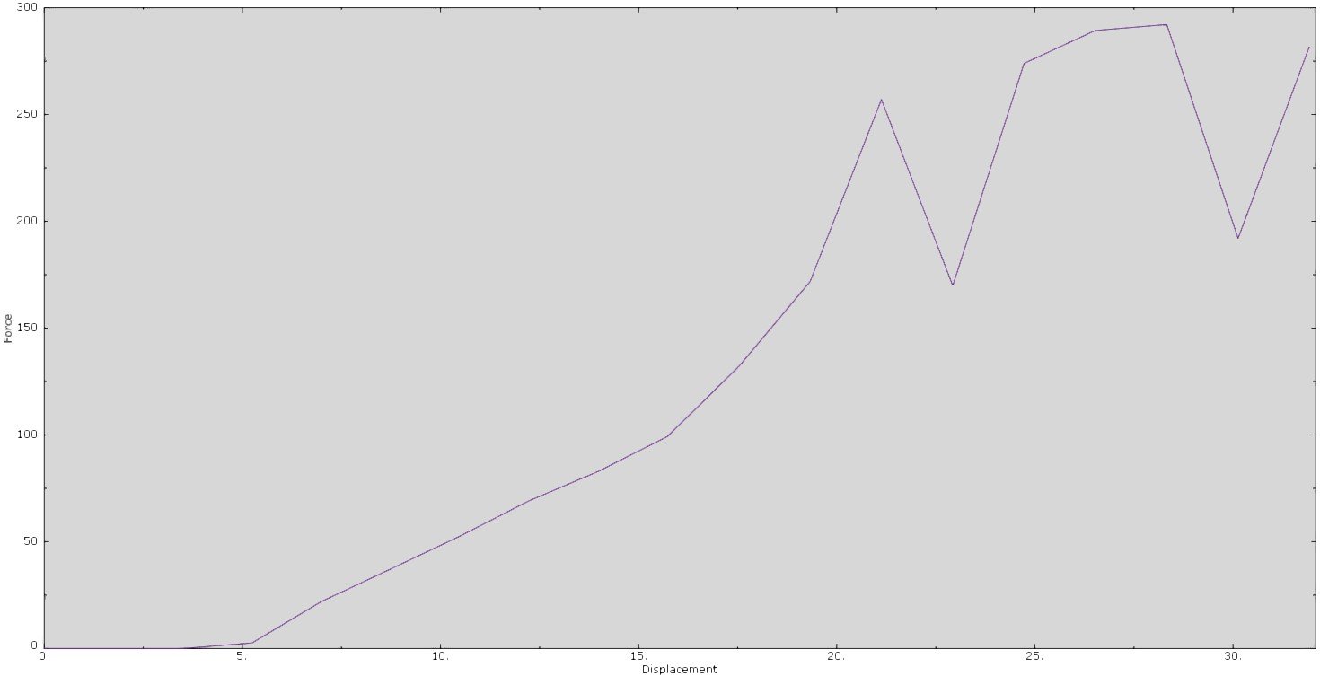
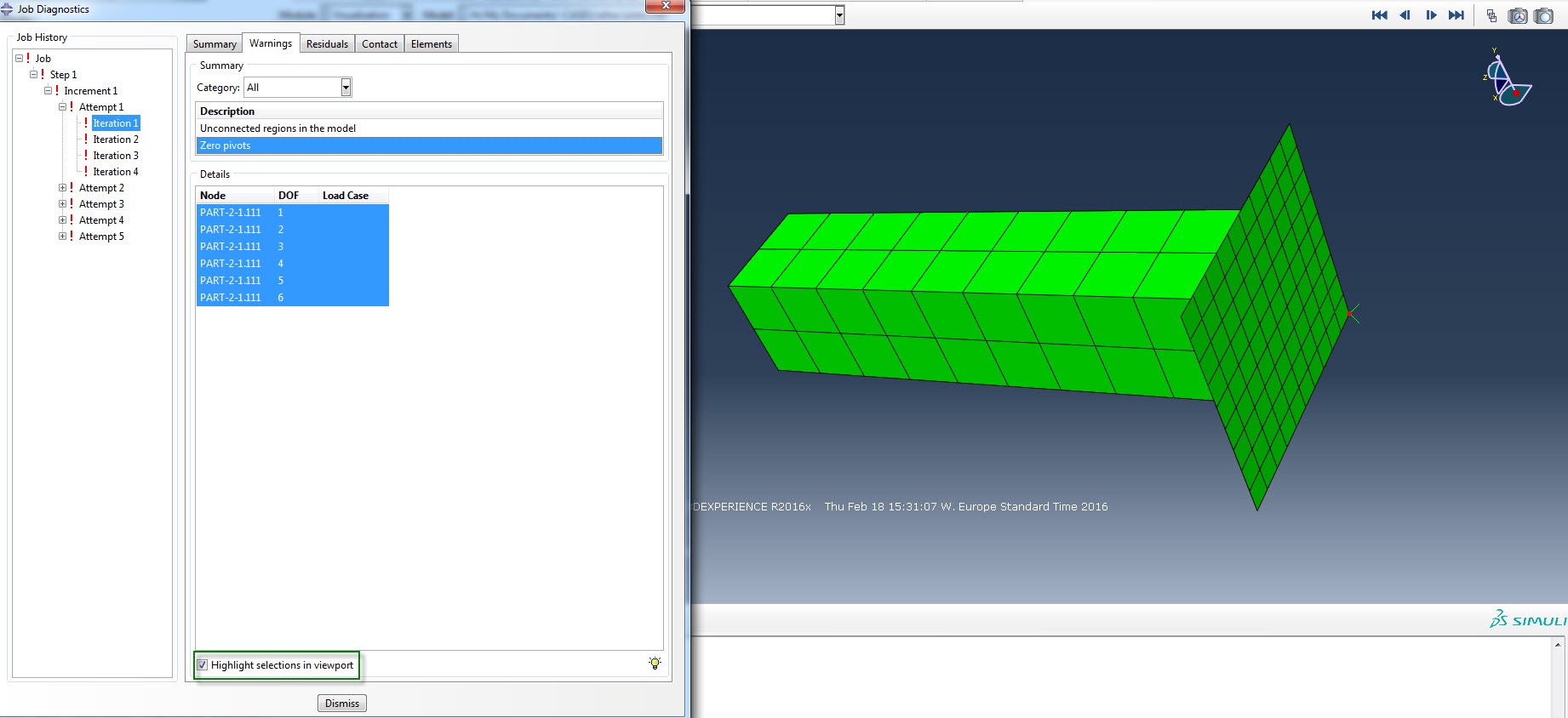
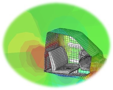
The first analysis unfortunately did not run until the full end (50mm displacement in Y-direction). So basically we did not find convergence. But we can still show the results up to that point and investigate why it did not converge. The first stress results look like this. See below.

As you can see from the force versus displacement graph, you can see the force decreasing after a displacement of ~6 mm. The curve also nicely shows the buckling starting point(s).

See video below for the animated result.
9. Switching to Explicit
In general, using Abaqus Explicit is a very handy way to discover what happened with the model when implicit could not converge. So we changed the step, changed the mesh elements to explicit, applied a tabular amplitude and run the analysis again. The results clearly show the reason for non-converging when using implicit. Due to the post buckling behaviour we see a buckling mode-swap in the area of the neck of the bottle taking place. These typical mode swaps behave very dynamically and therefore should be calculated with an Explicit solver. In order to obtain the crushing load analysis, the only thing you have to do is to enlarge the pre-described displacement, and probably reduce the total analysis time, because that is a typical high speed event.


See the video below for the dynamic buckling mode swap behaviour.
10. Squeeze Load Analysis
In the squeeze load analysis we basically undertake the same steps as with the explicit analysis, but we have added two surfaces that represent the analytical fingers on which we will apply the pre-described displacement. Again, we will be measuring the force versus displacement. See results below.

See video below for the simulated results.
Want to share experiences on your challenges with your FEA models for plastic packaging and benefit from our experience?


TECHNIA Simulation provides top tier FEA, Non-linear, and Advanced Simulation Software, Training, and Consultancy. Our dedicated team of more than 65 Simulation experts across 16 countries advise and support your innovation with a wealth of specialist knowledge and experience.
About TECHNIA- Related news and articles straight to your inbox
- Hints, tips & how-tos
- Thought leadership articles

Helping you find the information you’re looking for. Discover webinars, events, FAQ's, case studies and tutorials.
VIEW HUB