
Posted by Christine Obbink-Huizer
Table of contents
Sometimes you have a mesh in Abaqus, and you don’t have the corresponding geometry. Abaqus offers tools to create geometry based on a mesh. Here I will discuss two options: using the mesh-to-geometry plug-in and using the built-in tools. I’ll explain the difference and when to choose which option.
Introduction
In Abaqus, you may have a mesh without the corresponding geometry. This can happen if only the .inp from an older model is available, if you want to use the deformed shape in an .odb as starting point of an analysis or if the geometry comes from an external system that only provides mesh(-like) information. In Abaqus it is possible to work directly on the mesh, and set up an analysis without having geometry at all. There are even some options to modify such an orphan mesh (a mesh not connected to parent geometry) in Abaqus/CAE. Having the geometry offers a lot more control over the mesh on the part. Here I will show how geometry can be derived from a mesh.
Example Geometry
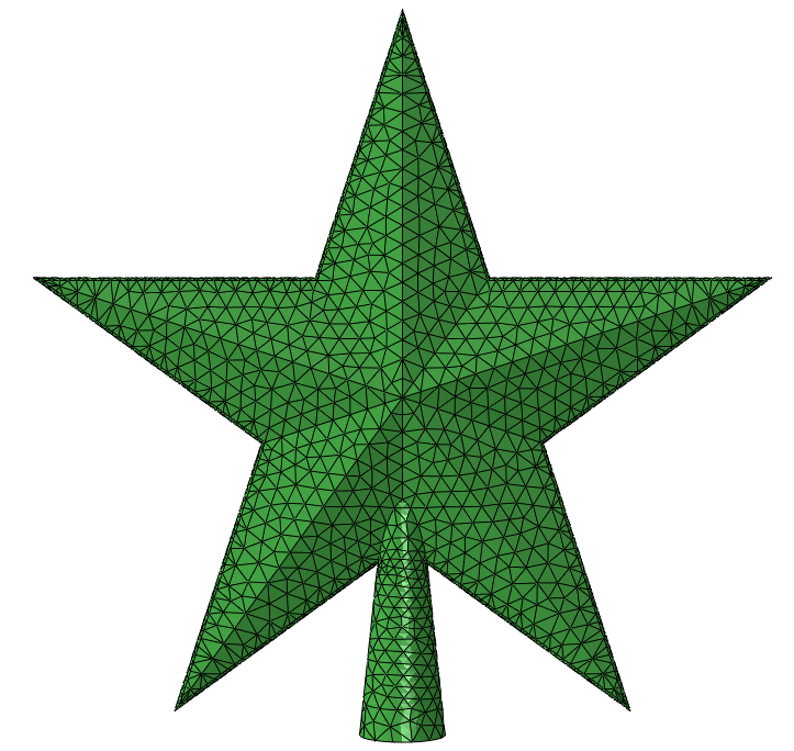
As an example, I will use this star-shaped Christmas tree topper. It’s meshed with tetrahedrals, and I’ve created a mesh part (orphan mesh) from it (Figure 1).

Figure 1: The orphan mesh. Note the green colour that is typically used to display orphan meshes in Abaqus.
Approach 1: Mesh-to-geometry Plug-in
Some years back, before the built-in Abaqus functionality existed, some one at SIMULIA developed a plug-in to convert mesh to geometry. This is still available.
The plug-in can be used on either an .stl file, or an orphan mesh. This plug-in creates a geometrical face, for each external element face in the mesh. There is an option to try to add volume, so a solid part (rather than a shell representing the outer surface) is obtained. It may take a while to run. The result for the example (Figure 2) looks similar to what we had before (Figure 1).
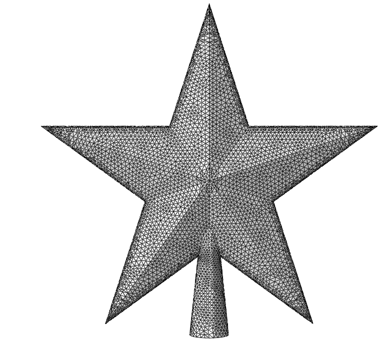
Figure 2: Resulting part that is output from the mesh to geometry plug-in. The grey colour indicates this is geometry rather than a mesh.
The geometry has geometrical face corners at all nodes of the mesh. Since quadratic elements where used, the faces on the geometry are smaller than the elemental faces.
Does this bring us anywhere? If we would mesh this geometry, the new mesh is still controlled by the original mesh, and the elements will be even smaller. It would make more sense to directly work on the mesh then.
Since this is now geometry, we can use geometry edit tools, as well as virtual topology on it. Abaqus has options to replace several faces by a single face (geometry edit), or to neglect certain edges when meshing (virtual topology). By using these features one can create several larger faces for meshing, allowing more control over the mesh.
Postprocessing: Geometry Edit
For example, by using the replace faces option, the geometry was simplified to what is shown in Figure 3. It is easy to select multiple faces when using the ‘by angle’ option. Though it takes time for Abaqus to calculate the new face, the user effort is limited.
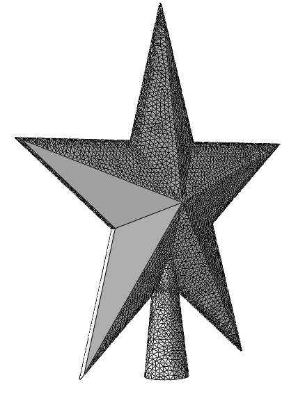
Figure 3: Geometry after apply ‘Replace Faces’ several times. It would be possible to replace more faces, but due to the time it took to replace the faces, it was not done in this case.
A second approach it to use Virtual Toplogy. In this case the geometry is not changed, but some edges and/or vertices are not used for meshing: the requirement to have element edges and nodes at those locations is removed.
Postprocessing: Virtual Topology
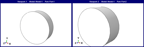
Using virtual topology, we can obtain a geometry such as what is shown in Figure 4 (left).
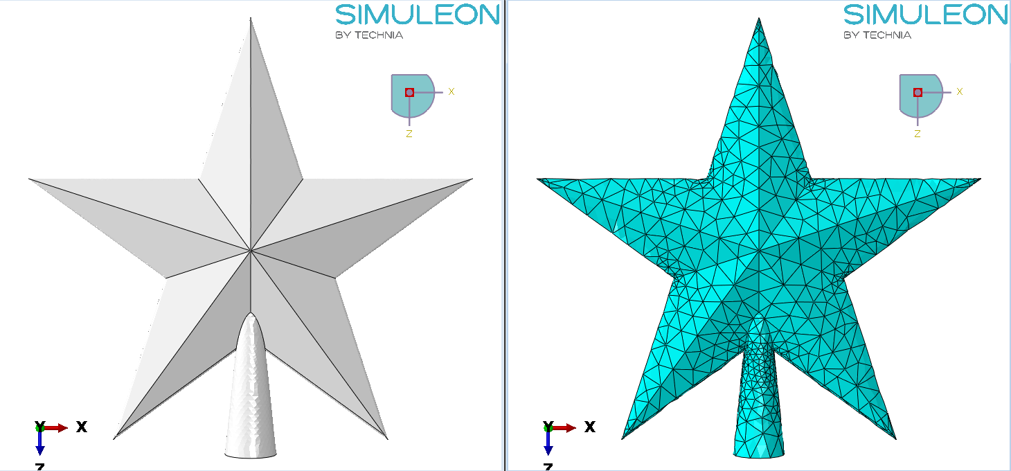
Figure 4: Geometry after virtual topology (left) and example mesh with less seeds (right).
This can then be meshed using mesh seeds determined by the user, so the mesh can be coarser than it was originally (Figure 4, right).
Depending on the edges that are or aren’t abstracted away, the results will differ. By keeping edges, the mesh will better follow the geometry in that region and local mesh seeds can be controlled.
Approach 2: Built-in Utilities
Abaqus currently also provides a built-in tool to create geometry from element faces.
The faces to be converted to geometry are selected. If multiple elemental faces are selected at the same time, one geometrical face will be created. This is different compared to the plug-in, which is applied to the entire part, and creates triangular faces between all of the nodes.
If this option is used with e.g. the face selection by angle option, then with a few clicks several larger surfaces can be created. For the flat faces on the front and back of the start, this works very well. The cone-shaped section on the bottom can also be converted (Figure 5).
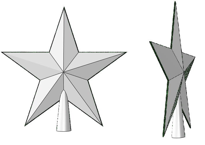
Figure 5: Orphan mesh with geometry created on it using the built-in tools.The larger faces can easily be converted.
If the faces represent a smaller radii, then they may not be continuous, and it tends to be more difficult to combine element faces. Often Abaqus can only create a face when just a few faces are selected. A lot of manual effort is then required to transform all elemental faces into geometrical faces. Also, geometrical faces do not always fully connect automatically (Figure 6, left) and additional manual effort such as stitching may be needed to solve the issue (Figure 6, right). The same techniques mentioned for the mesh to geometry plug-in can be used to combine geometrical faces once all elemental faces have been converted to geometrical faces.
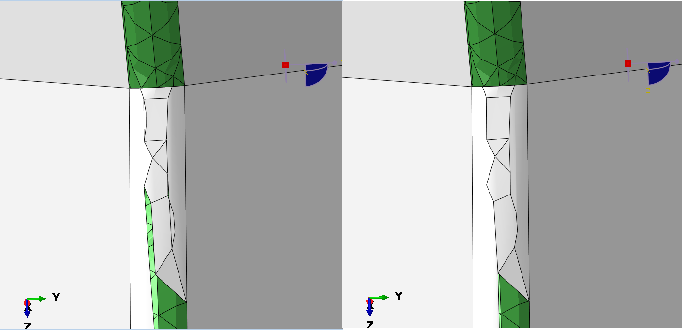
Figure 6: Converting element faces to geometrical faces using the built-in tools for faces with a small radius. Small faces are required and gaps and overlaps arise (left). These can be removed by stitching (right).
Comparison and Conclusion
Working with meshes and converting mesh to geometry is possible with Abaqus, but never extremely user-friendly. To convert mesh to geometry, two options are available: using a plug-in and using the built-in option to create geometrical faces from elemental faces. The plug-in converts the entire part at once to small faces. This typically means the resulting geometry needs to be postprocessed afterwards to make it useful. Virtual topology is very helpful for this.
The built-in options can convert multiple elemental faces to one geometrical face. For flat surfaces this works well and is more efficient than the plug-in because it does not require postprocessing. For elemental faces that are not continuous, it is more difficult for Abaqus to combine multiple elemental faces in a single geometrical face. In this case a lot of manual effort may be needed to obtain the geometry of interest. If that is the case then the plug-in, in combination with virtual topology, may be more efficient.
Extend your simulation capabilities, discover our upcoming training courses!


TECHNIA Simulation provides top tier FEA, Non-linear, and Advanced Simulation Software, Training, and Consultancy. Our dedicated team of more than 65 Simulation experts across 16 countries advise and support your innovation with a wealth of specialist knowledge and experience.
About TECHNIA- Related news and articles straight to your inbox
- Hints, tips & how-tos
- Thought leadership articles

Helping you find the information you’re looking for. Discover webinars, events, FAQ's, case studies and tutorials.
VIEW HUB