The Abaqus implicit and explicit solvers are known for their comprehensive capabilities for solving a range of mechanical simulation scenarios, but especially when that problem is non-linear. In a mechanical context, that non-linearity could come from the change in geometric stiffness as the model deforms, the material response, or the ‘boundary non-linearity’, which is (more often than not) manifested as the contact state between parts of the assembly being simulated changing as the solution evolves.
Over the last several releases of Abaqus, significant development effort has been put into closing functionality gaps between the traditional ‘Contact Pair’ approach to defining and tracking contact in Abaqus, and the ‘General Contact’ approach, which started in Abaqus/Explicit but has over time migrated to Abaqus/Standard. With the improvements in capability, robustness, and overall performance, ‘General Contact’ is increasingly the go-to method to specify contact interaction properties, and then leaving it to the solver to work out when to apply them is the most efficient way as the solution proceeds.
For those that follow the development arc of Abaqus (and maybe take time to read the release notes to go with each new version), none of this is perhaps ‘news’ at a high level, but there is also still new functionality being added that moves specific workflows forwards. For an example of such an improvement, consider the case of defining contact between a beam element and an adjacent surface. In this workflow, historically, the most robust way to handle contact with beam elements was to use a node-to-surface interaction, where the node-based surface was formed from the underlying beam elements: it worked, but it completely ignored the shape of the section applied to the beam elements. However, for quite a while now, the user has also been able to use a ‘circumscribed circular’ profile to approximate the contact surface of the section to a uniform rod-like profile: better, but still not ideal, especially given the richness of the built-in section profiles that can be defined in Abaqus.
Things have moved forwards again as of Abaqus v2023, where the user can ask the solver to use the exact profile assigned to beam elements to define the contact surface with adjacent bodies, which is quite an improvement. No longer does the user need to mesh a noncircular shape in 2D or 3D to create a contact surface, it can all be done analytically in 1D. Better than that, it’s a single button click to activate this when configuring the general contact domain in the GUI or keyword option, as shown below.

Figure 1 – General contact exact beam cross section activation options
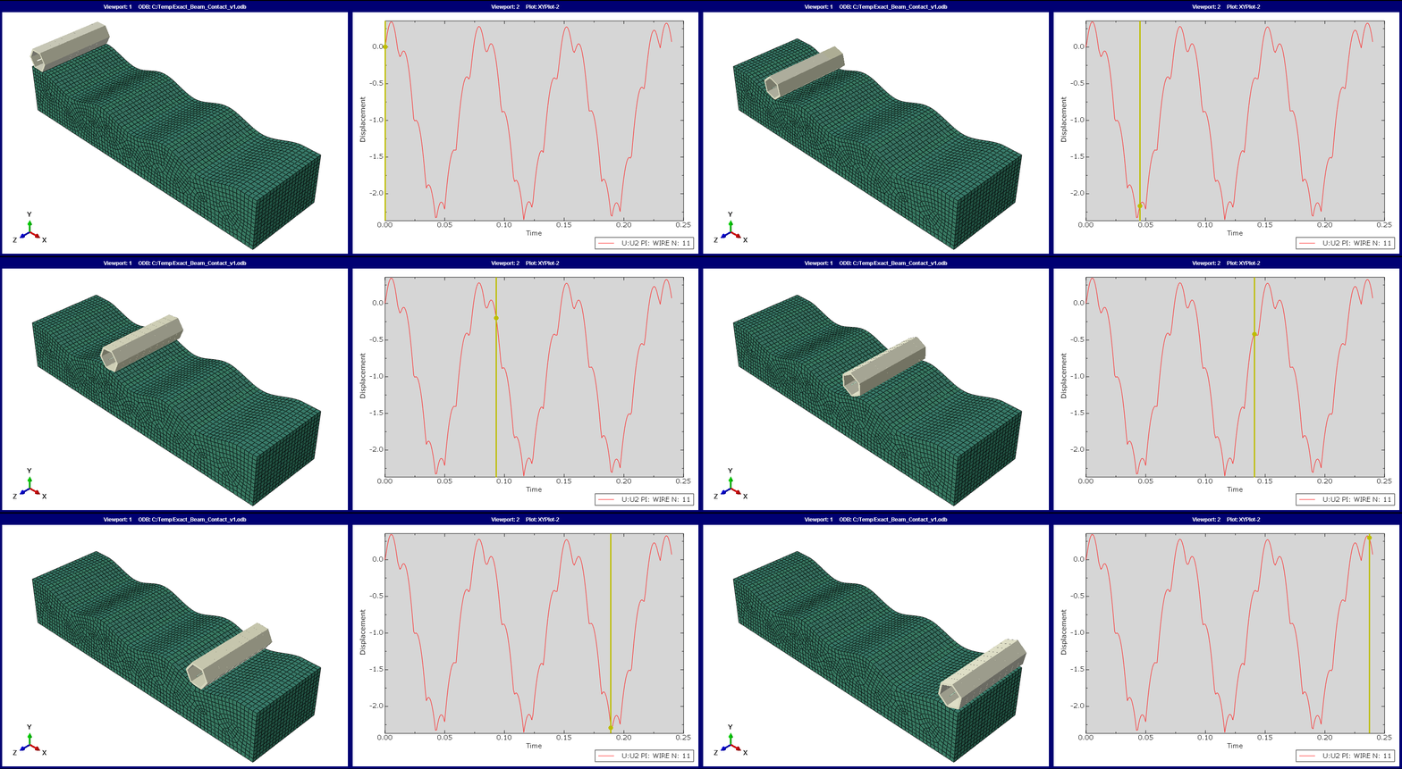
All of this is pulled together in the example below, where a beam element with a hexagon profile is rolled over a very non-uniform surface. The hexagonal shape that is visible is the defined profile rendered geometrically on the underlying beam element, to be able to see what’s going on. Also, ‘General Contact’ with the ‘Beam Cross Section Assignment’ option is enabled, as shown above, at the interaction between the bodies. In this case, one general contact/’ALL EXTERIOR’ definition copes with all of this complexity in (genuinely) just a few button clicks.

Figure 2 – Example general contact model including exact beam cross section option activated
To illustrate that this produces a mechanically correct response, the linked graph shows the vertical displacement of one node on the line of beams as it rises and falls due to the profile of the adjacent body, plus the corners of hexagon causing the additional bumps in the output.
This is just one example of the capabilities of Abaqus being improved and extended with every new release, but there are many more. If you'd like to keep learning more about Abaqus, or have questions about how best to run your simulations, why not check out our Continual Learning Program or get in touch with a TECHNIA Simulation expert today?


