 What Is a Coating?
In many engineering applications the role of a coating layer is a key factor for determining its performance. The concept consists on applying a superficial cover to the substrate (ground material). Such coating is typically a few microns and will determine the distinctive characteristics of the product.
Why to Use Coatings?
Different goals can be pursued when using engineering coatings: examples include preventing and controlling wear and friction in tribological applications or wear and resistance in structural mechanics; aiding in corrosion prevention for parts working in aggressive environments; as a deposition to repair surface damage. The applications are numerous but we will not extend further in that topic, even though the type of coating and its purpose can be different the basic concept is still the same, i.e. a base material that has a characteristic material in its surface.
Current Problem in the Design of Coatings
The engineering coating technologies fight for its portion of a very competitive market, in such market minimizing development costs can make the difference on the road to success. Because creating prototypes and subsequent experiments to evaluate its behaviour can be not only a laborious and time consuming task but also fairly expensive other means to aid in the development without incurring in large costs should be considered.
General Solution
In the past years the approach has shifted from more physical testing to virtual testing. Thus the physical testing only takes place as a final stage in order to verify assumptions and validate the models. Following such trend we currently propose to use finite element analysis (FEA) to assist on the first stages in the development of coated products and have an accurate estimation of its performance. Hence sparing in experimental trials, time and resources.
Proposed Solution
In the field of FEA Abaqus (Dassault Systèmes Simulia Corp.) has set a landmark because of its robust solvers, its capabilities and strength to solve non-linear problems and its cutting edge technology.
Abaqus includes features that can definitely help in the current hot topic. In Abaqus a functionality called skin allow for the creation of a very thin layers on top of a base material. These layers can have different material properties than the ground material. Typically, the properties of the coating/skin are the ones that will determine the distinctive properties of the product.
The generation of a skin is relatively simple process. You only need to select the surface where the skin wants to be generated. No further definition of how the surfaces are bonded to each other is required. The process where more details can be given to this layer comes when the material properties and thickness are assigned through the section assignment in the property module.
Example
In order to illustrate the process I have picked from www.grabcad.com an insert from a milling tool. The latter is a typical product that often requires coating deposition to increase it mechanical properties and reduce friction hence increasing it performance.
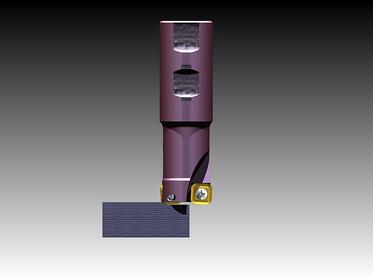
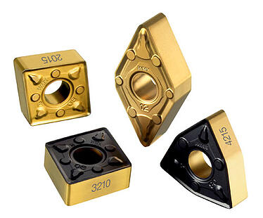
Figure 1: Rendering of the tool including the golden inserts that were used in the current FE model. CAD model and renders obtained from https://grabcad.com/library/cutter-bodie-and-inserts-for-milling.
The insert is subjected to a force created when cutting the material. Such force is only in one of the cutting corners. The bottom face is fixed in space. In this a simplified process milling process could be simulated.
For the current blog the focus was on the definition of the skin. Therefore a more detailed description will be given below.
Guideline to create a skin and assign material properties:
- Make sure you are in the Property module
- Select from the main menu bar Special > Skin > Create… and then select the surface of interest, holding “shift” to add multiple surfaces.
- Create a section of type shell Section > Create > Shell (Category) and Homogeneous (Type). In this stage you will be able to specify , among others, the thickness and the material properties.
- In order to have only the skins visible to assign the section from the drop down menu on the top bar select Skins and select all the skins that you are interested in.

You can select the full model if you have only one skin. Then click on Replace Selected  and only the skins should be visible.
- Assign the section recently created: Assign > Section and click on the skin of interest. The skins have now the materials properties and thickness assigned.
In a simple and default view the part does not look like any coating has been applied, Figure 2.
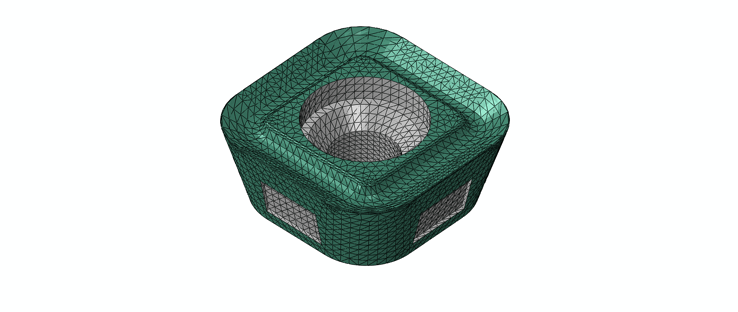
Figure 2: Blank insert where a skin (green) has been created on top of the base material to simulate a coating. The figure shows that besides the difference in color the skin is not seen as extra thickness.
However, the fact that the skin is not clearly observed is only a visualization effect. By rendering the thickness of shells the coating can be observed, Figures 3-4.
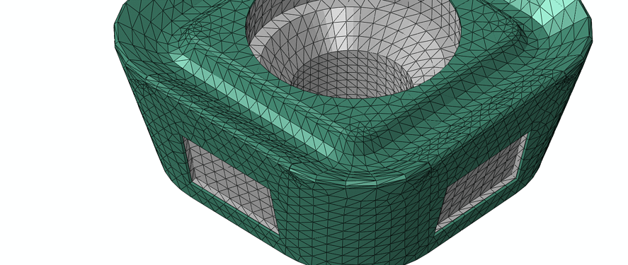
Figure 3: Close up where the rendered thickness can be observed. Notice that now the green layer has a thickness that was not observed before.
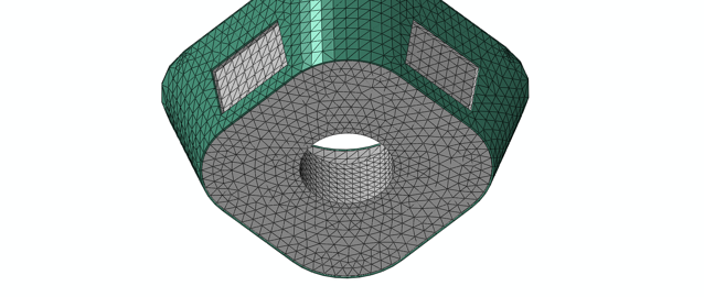
Figure 4: Detailed from the bottom showing the thickness of the coating layer. The green skin has a uniform thickness that can be clearly distinguished from the bottom view.
When talking about the elements to mesh the skin it needs to be said that the skin cannot be meshed individually. Abaqus will generate elements with nodes coincident with the nodes from the underlying material, Figure 5.
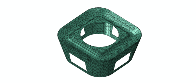
Figure 5: Elements created on the skin; they have the same shape of the underlying element. The user has control over those elements only by changing the elements of the base material.
The elements that can be used to discretize the skin can either be shell or membranes with the latter having no stiffness in bending.
Now you are ready to continue with the model definition and later run the analysis. Figure 6 shows an example when a force was applied on one of the corners of the insert simulating a machining process.
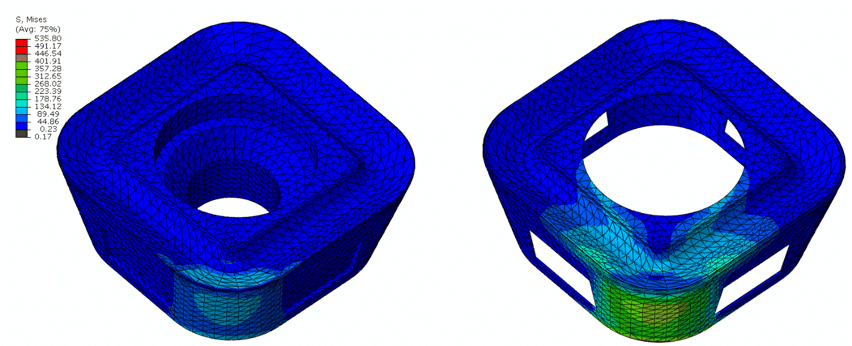
Figure 6: Particular stresses on the base material and on the coating.


 and only the skins should be visible.


