
Posted by Ebbe Smith
Table of contents
Abstract
In this article we’ll follow the process of setting up and running a condition-based topology optimization process in Abaqus. This is the most robust and easy to use approach. Nuances for further development will be discussed as we go along. After reading this article, you should be able to elevate your Abaqus skills to produce organic load-driven designs.
Introduction
We’ve all seen them, these impressively organic and complex structures that nature makes. In recent times, engineers have been able to recreate this process. Traditionally, product development is a CAD driven design process where industrial designers perfect form and shape, while mechanical engineers realize them, addressing the structural requirements.

Figure 1: Incredible leaf structure. Photo by: Maros Misove (Unsplashed)
Topology optimization is a way of distributing mass inside an available area which encompasses all the space available for the component to occupy. By supplying information about material properties, component symmetry, manufacturing constraints and loads which the component is to be subjected to, design candidates that satisfies the design objectives are automatically generated by topology optimization algorithms. These design objectives are famously known to provide the highest stiffness to weight ratio, or to “minimize compliance”, as it is popularly called by engineers. It is worth noting that the design objectives can be stress values at a specific region, displacement in a node, eigenvalue, and much more. Same goes for manufacturing constrains, where you can easily use topology optimization for castable, machinable designs too.
Case study: Whiteboard Penholders
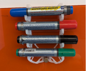
Figure 2: Topology Optimised Penholder
In our office we have a 3DPrinter. One of my first projects was to create a customized penholder for my whiteboard, using topology optimization. It’s a great, yet simple case, to get a few points across, so let’s use it as an example.
In the following post we’ll investigate how to:
- Create and modify the design domain
- Develop a representable FEM analysis as a basis for topology optimization
- Define and run a topology optimization study
- Extract and smooth result
- Send it to the 3DPrinter
1. Defining the Design Domain
Design domain in topology optimization encompasses all the space where material can be put to satisfy the objective function and constraints, which is classically maximizing stiffness for a given amount of material. More on this later.
Functionally our domain must satisfy these requirements:
- Have room for the whiteboard pens
- Allow pens to be put straight in – as a katana sword on the rack, in lack of a better description.
A key observation is that the penholder is to be hanged on the whiteboard, so we need to find the dimension of this edge, and include this in our design domain.
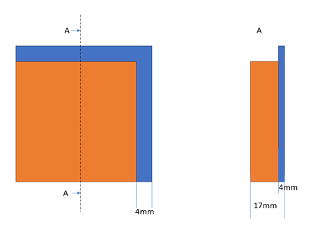
Figure 3: Whiteboard Dimensions
From this, we can start to offset the pens to get an impression of how big the design domain should be. After looking on the results in figure X, it makes sense to add a magnet to help stabilize the bottom of the holder from shear forces caused during interaction – space for this magnet results in a 3rd requirement for the design domain.
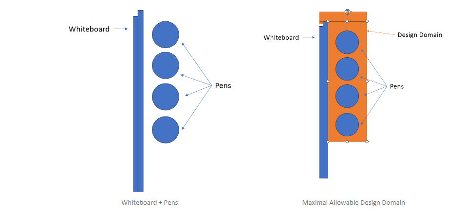
Figure 4: Maximal Allowable Design Domain
The resulting design domain is of a quite simple geometrical shape and could easily be created entirely in Abaqus/CAE. A bonus benefit is the ease of modification of this domain at a later point.
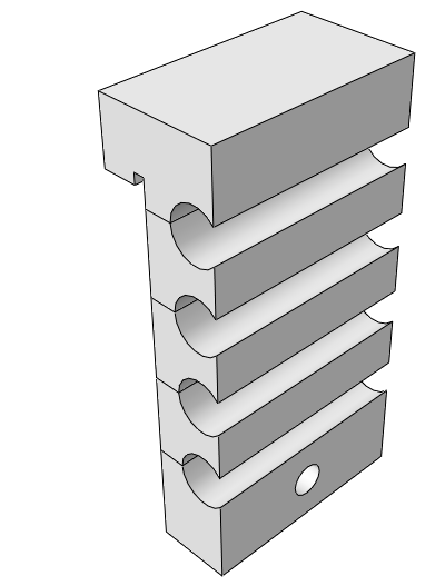
Figure 5: 3D Modelled Design Domain
This domain satisfies all our 3 requirements.
Next step is to load this design domain, before performing the Topology Optimization study.
2. Representable FEM Model
This step presents an opportunity to review loads and make last minute changes. I personally prefer to create initial models that leverages accuracy and performance with an emphasis on the latter. In this case, we can utilize symmetry constrains and keep it linear.
For material modelling, I’ll just use some approximate PLA linear elastic material. Boundary condition will be modelled as performing the expected functions. The lip on the back end of the whiteboard will be constrained for forward motion. Magnet slot will constrain shear movement. Pens will be modelled as pressure loads on the outer ends of the penholder.
I’ll add two accelerations, gravity and then one extra to account for interaction of me hurriedly fetching and displacing a pen. This is how I chose to model the dynamic event of quite undefined interaction to force the topology optimization algorithms to see the need for cross-braces or other stabilizing structure for lateral motion. It won’t be created if there is explicit need for it, which is a major consideration when setting up loads and BCs – do they accurately represent loading scenarios?
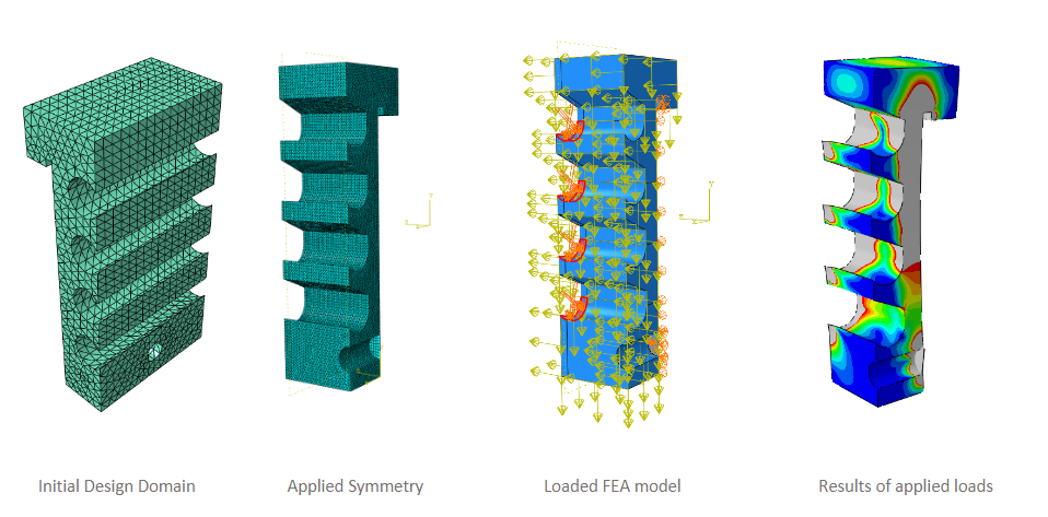
Figure 6: From initial design domain to results from a loaded symmetrical FEA model
By keeping the model symmetrical, linear with effective loads and boundary conditions we have an efficient FEA model which can be used for further analysis.
3. Define and Run a Topology Optimization Study
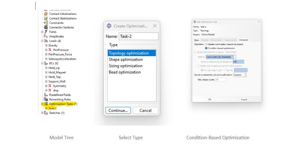
Figure 7: Defining a condition-based optimization task in Abaqus/CAE
In the Abaqus model-tree, we double-click “Optimization Tasks”. We are going to setup a condition- based optimization that uses strain-energy as objective function, and volume as a constraint. This task is the easiest to setup and run, and is great for maximizing stiffness for a given volume.
Condition-based optimization provides only two design responses (or design variables). They are representable for the whole design domain, and are “Volume” and “Strain Energy”. All optimization processes need an objective and constraints for the design variables.
Objective Function: Minimize Total Strain Energy (Maximize stiffness)
Constraint: 5% of initial value
In Abaqus, we need to create Design Responses, as well as to create an Objective function, and our constraint.
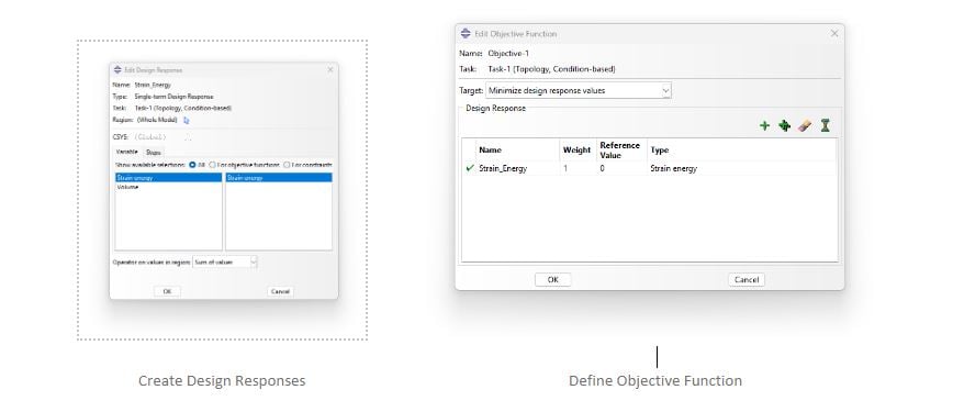
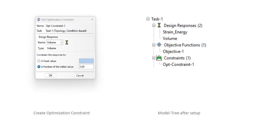
Figure 8: Topology Optimization Setup
If symmetry, or any other geometrical considerations, need to be addressed, such as manufacturing requirements (symmetry, demoulding directions, tool access for machining, thickness for members), it is implemented with Geometrical Restriction. This ultimately means that this approach can be used for traditional manufacturing.
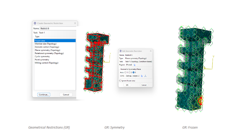
Figure 9: Geometrical Restrictions
A geometrical restriction is needed for the symmetry, and then one to freeze the material concerning the magnetic holder. While the constraints could just as easily be added to the edges, this was the way I opted for.
Without further ado, let’s run the topology optimization! In the model tree we click “Optimization Process” under the analysis branch. Note that models can have several optimization tasks, where you can experiment with different setups and algorithms.
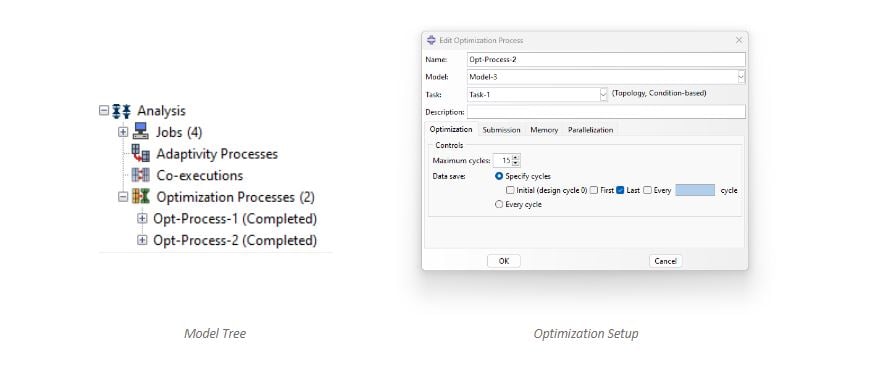 Figure 10: Create Topology Optimization Job
4. Extract and Smooth Results
As constraints are applied over several cycles – element density changes and reveals critical load paths.
As elements can have several densities – visualization is created by using ISO surfaces in the density field.
Elements with a relative density below the cut value is discarded, revealing the optimized elements with high enough density.
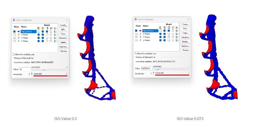
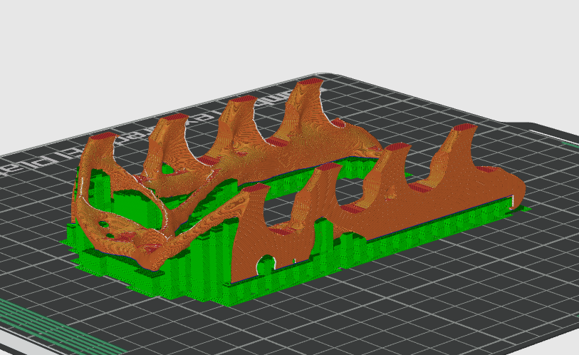
Figure 12: Optimized Iso-surfaces
The viewed result is based on element results, providing only a preview. Global smoothing is performed by extracting mesh where smoothing parameters is provided.
Note that it is possible to select both cycle and iso-value to start mesh extraction (right-click optimization process in the model tree). It is highly recommended to look into the documentation (Search “Extracting a smoothed mesh”) for an explanation of the advanced parameters, as they are vital to create good looking meshes for further processing.
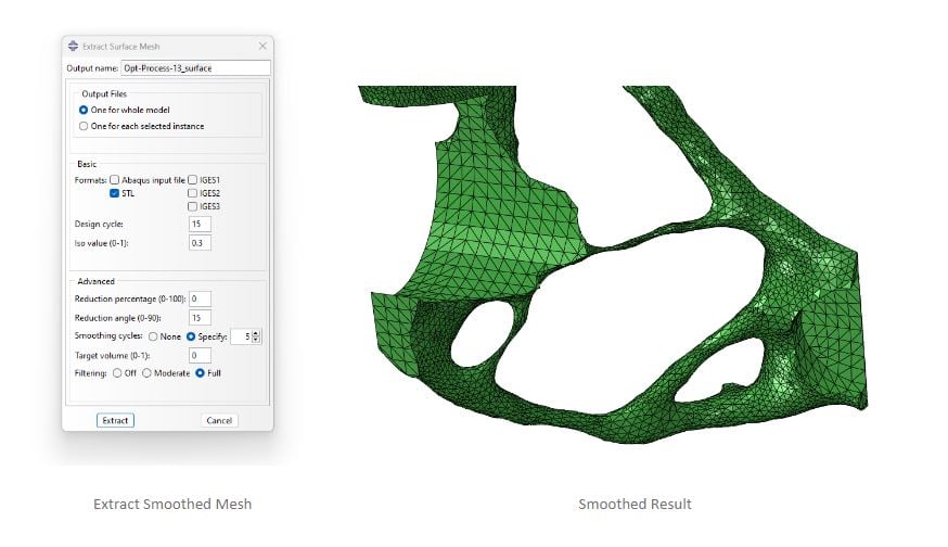
Figure 13: Smoothed Result
Resulted smoothed geometry is shown below and is exported as an STL file for further processing, before it is sent to the 3DPrinter.
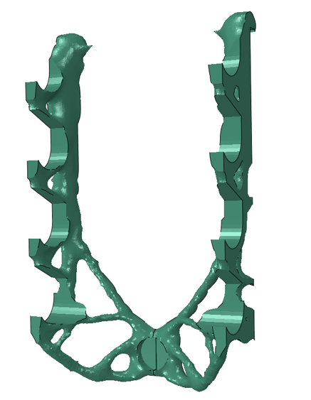
Figure 14: Smoothed Topology Optimization Result
It is worth noting that at this point, the workflow has a natural breakpoint. Usually, the prototype is printed, and small adjustments to the design domain or study will invoke a more suitable optimization, adding more load cases for robustness or functional changes, such as making more room for the pens.
If not, it is often recreated as a CAD model – which often is a complex and time-consuming job (check out Functional Generative Design on the 3DExperience platform!). Drawing creation for manufacturing gets to be quite laboursome. However, the quality of a few iterations of topology optimized driven design can be miles ahead traditional process, but this is where you pay the price.
For direct prototyping, we can luckily send it straight to the printer.
5. Send to 3DPrinter
As a relative rookie in the 3DPrinting world, we have an easy-to-use FDM printer which has an integrated slicer and monitoring tool. I can drag and drop the STL file, and then slice its based settings for supports, and so forth.

Figure 15: Sliced STL file
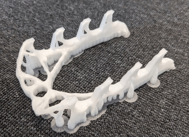
Figure 16: Printed Component with Supports
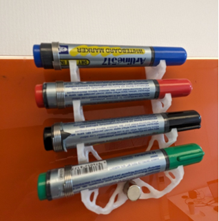
Figure 17: Tidy whiteboard at last!
Closing Remarks
Working with topology optimization requires a solid understanding of all possible loads that are, and can be, subjected to the component at hand. The more aggressively the optimization is, the more fragile the part is, if subjected to loads outside the defined behaviour. This is mentioned to show that results of topology optimization should be subjected to best-practice rigours engineering and not be taken at face value, while this technique allows a short-cut to design high performance components it.
There are other forms of application of topological optimization, where instead of element relative density, thickness and sizes are the variables. Minor adjustments to specific geometrical changes can also be applied to increase fatigue life.


TECHNIA Simulation provides top tier FEA, Non-linear, and Advanced Simulation Software, Training, and Consultancy. Our dedicated team of more than 65 Simulation experts across 16 countries advise and support your innovation with a wealth of specialist knowledge and experience.
About TECHNIA- Related news and articles straight to your inbox
- Hints, tips & how-tos
- Thought leadership articles

Helping you find the information you’re looking for. Discover webinars, events, FAQ's, case studies and tutorials.
VIEW HUB